5
PREPARATION (Continued)
Check area above installation location to be sure that wiring can run to the planned location and that duct work can be run
and the area is sufcient for proper ventilation.
Inspect duct work and wiring before proceeding with installation.
Before installation, provide inspection and future maintenance access at a location that will not interfere with installation work.
IMPORTANT: Attic access is required for proper installation. You may need the help of a second person to install this fan:
one person on the attic side and one on the room side.
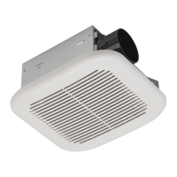
Installation may vary depending on how the previous bath fan was installed. Supplies necessary for the installation of your
bath fan are not all included; however, most are available at your local home improvement or hardware store.
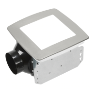
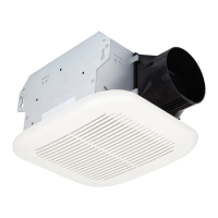
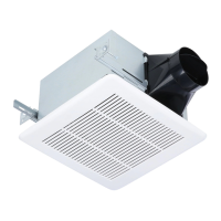
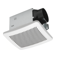
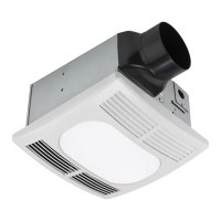
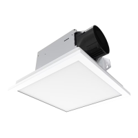
DIMENSIONS
Ceiling
Opening (L)
Ceiling
Opening (W)
Ceiling
Opening (H)
Housing
Dimension (L)
Housing
Dimension (W)
Housing
Dimension (H)
9-1/4 in. 9-1/4 in. 6 in. 9 in. 9 in. 5-25/32 in.
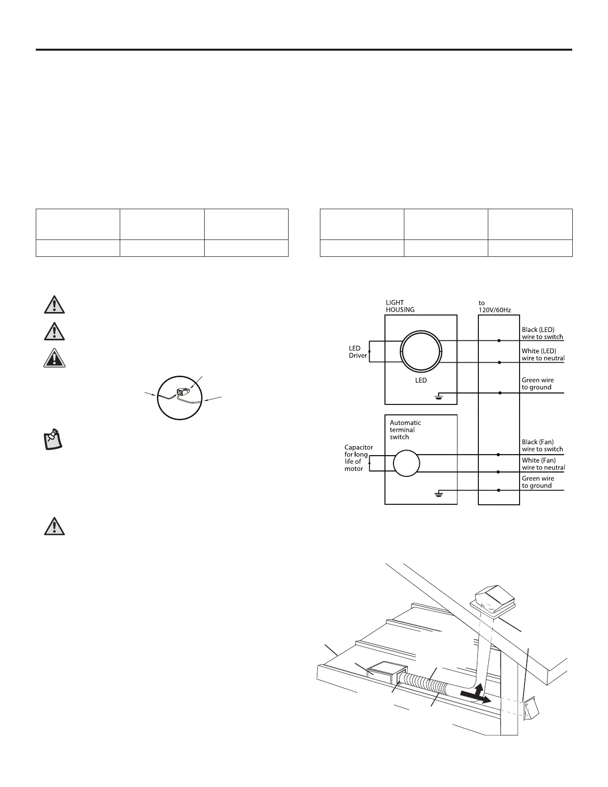
WIRING
WARNING: Wiring must comply with all applicable electrical
codes. Turn off power before removing or installing connectors.
WARNING: COPPER TO COPPER ONLY. Do not use
aluminum wire.
CAUTION: Accessory part (quick connector) should meet
installation instructions below.
House
wires
Product
wires
NOTE: The connector is reusable on solid wires of the same wire
gauge or smaller. Donot reuse the connector on stranded wires.
• Strip wires 3/8 in. - 1/2 in.
• Grip the wire rmly and push the stripped end of the wire into the open
port of the connector. Use only one conductor per port.
• Verify the stripped end of the wires is fully inserted to the back of the
connector.
CAUTION: Wiring maximum temperature rating 221˚F (105˚C).
600V maximum for building wiring and 1,000V maximum for signs
and light xtures. The acceptable wire range is 12-18 AWG Sol. Cu.
Quick
connector
It is recommended to apply proper insulation around the
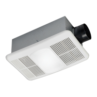
fan to minimize heat loss and gain. This fan is designed to
be installed using a 4-in. duct.
Using a rigid duct is recommended. Using a exible duct,
cut to size and/or fully extended is also acceptable.
Ducting has a strong effect on the air ow, noise and
energy use of the fan. Use the shortest, straightest duct
routing possible for best performance. Avoid installing the
fan with smaller ducts than recommended. Insulation
around the ducts can reduce energy loss and inhibit mold
growth. Fans installed with existing ducts may not achieve
their rated air ow.
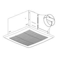
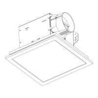
TYPICAL INSTALLATION
Fan housing
Properly insulate
around fan to
minimize building
heat loss and
gain
Seal any gap
around fan
housing
2-3 foot
straight run
before elbow
Short piece of
exible duct helps
alignment and
absorbs sound
Roof cap
(with built-in
damper)
Caulk
termination
to duct
Wall cap
(with
built-in
damper)
OR