FUNCTION TABLE PD2
48
N. DISPLAY DATAS DESCRIPTION DEFAULT
DATAS
MEMO
DATAS
13 Ch.AU
no
t.PAU
Automatic closing
- automatic closing not available
- reclosing is available, the standstill time is set
from 0 to 999 s
No
14 LUCi
CiCL
t.LUC
AUS
timer
bISt
Mon
Courtesy light
- lights are on trough the whole cycle
- lights start time adjustable from 0 to 999 s
- auxiliary output
--- timed aux out (from 0 to 999 s)
--- aux out relay with bistable functionning
--- aux out relay with monostable functionning
t.LUC
=60 s
15 LP.PA no/Si Flashlight in pause no
16 In.LP no/Si Flashlight with intermittence no
17 OroL no/Si Clock function no
18 FrEn no/Si Brake no
19 StoP
no
invE
.
ProS
Input STOP
- input STOP not available
- input STOP stops the gate: pressing the
command START gate continues the motion
- STOP command stops the gate: START
command starts moving in the opposite direction
no
20 Fot 1
no
APCh
Input PHOTO 1
- not available
- photocell active during the opening & the closing
no
21 Fot 2
no
CFCh
.
Ch
Input FOTO 2
- not available
- input available: photocell is active in closing and
also when the gate is still
- input available: photocell active during the
closing
CFCh
22 CoS1 Si/no SAFETY RIB1 input Si
23 Cos2 Si/no SAFETY RIB2 input Si
24 FCA Si/no LIMIT SW. OPEN input Si
25 FCC Si/no LIMIT SW CLOSE input Si
26 tEL 1 Radio input associated to START command
27 tEL 2 Radio input associated to Ped START command
28 tEL 3 Radio input associated to STOP command
29 tEL 4 Radio input associated to courtesy light
30 Fine no/Si End of programming no
GB
49
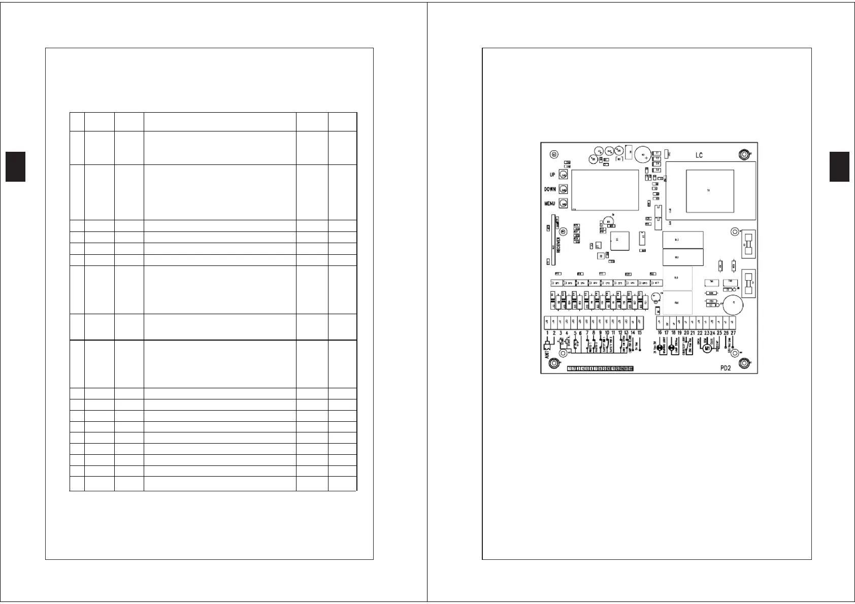
PCB AND CONNECTIONS
NOTE For the connection of the cables to the clamp, use the plastic
small band for the cables connected with the accessories and
for the cables connected with the supply power
GB
 Loading...