ENGLISH
11
L1 START/UP. N.O. contact
L2 STOP. N.C. contact
L3 COMMON (-)
L4 DOWN. N.O. contact
L5 PHOTOCELL. N.C. contact
L6
EDGE. N.C. contact
(Safety edge - parameter
in5 = oFF)
F
CA. N.C. contact
(Opening limit switch - parameter
in5 = on)
L7
FIRE. N.C. contact
(Alarm - parameter
in5 = oFF)
FCC. N.C. contact
(Closing limit switch - parameter
in5 = on)
L8 COMMON (-)
L9 Adjustment of the power for OPTICAL SAFETY EDGE
L10
30 Vdc power output for photocells and
other accessories
L11
30 Vdc power supply for functional test
TX photocell
E1 - E2
Flashing light 230Vac / 120Vac
(parameter
ou1 = oFF)
Courtesy light 230Vac / 120Vac
(parameter
ou1 = on)
E3 Motor open
E4 Motor common
E5 Motor close
N 230Vac / 120Vac power supply - neutral
L 230Vac / 120Vac power supply - phase
A1 Antenna shield
A2 Antenna
O
PTICAL EDGE INSTALLATION
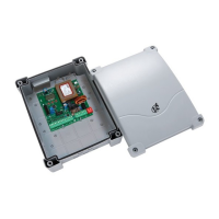
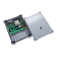
The EASY-TOP main control unit is configured for the installation
of one 24 Vdc powered optical edge and transmitter power
regulation.
Connect the transmitter and receiver in accordance
with the following table.
A
fter having made the connections, power-up the main control
unit and adjust the power using the trimmer TR1 located on the
control unit so as to obtain optimal edge operation.
FIRE / ALLARM INPUT
Safety input for connecting a fire or other type of alarm requiring
the immediate automatic opening of the door.
The FIRE command should be connected between the FIRE (L7)
and COMMON (L8) terminals.
When the FIRE contact is opened, the door is opened and cannot
be closed again until the contact is reset.
NOTE: If the input is set as an alarm (
in4 = oFF), when the FIRE
contact is open, the port cannot be opened. If the port is already
open, it is closed.
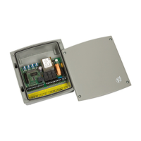
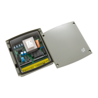
PLUG IN RECEIVER
The control unit is suitable for plugging in a MR receiver.
MR module receiver is provided with 4 channels and each of
them is suitable for a command of the control unit:
• CHANNEL 1
g
START/UP
• CHANNEL 2
g
STOP
• CHANNEL 3
g
DOWN
• CHANNEL 4
g
COURTESY LIGHT
m WARNING: Before programming 4 channels and
function logics read carefully the instructions of MR
TRANSMITTER RECEIVER
L6 BLACK CABLE
L8 BLUE CABLE BLUE CABLE
L
9
B
LACK CABLE
L10 BROWN CABLE
L11 BROWN CABLE