Vacon Plc Phone: +358-201 2121 Fax:+358-201 212 205
Service: +358-40-8371 150 E-mail: vacon@vacon.com
E-mail: application.team@vacon.com
Vacon Page 55
Pump control with autochange
9. 31 Autochange interlocks
With this parameter the use of interlocks can be activated. The interlocks come
from the switches that contact motors to the automatic control (frequency con-
verter), off-state or directly to the mains. The interlock signals are connected to
the digital inputs of the frequency converter. These inputs must be programmed
to interlock inputs. Each drive must have own interlock input.
Pump- and fan control controls only those motors whose interlock input is active.
If the interlock input changes to inactive or comes active again in Run state then
pump and fan control stops all motors and then starts control with new composi-
tion.
If the intelock of auxiliary drives comes true via RUN mode, operation depends
on par.9.35 setting. Default value is to restart the frequency converter and auxiliary
drives after STOP taking with the drives in the regulator system (dig. input =
ON). See par.9.35.
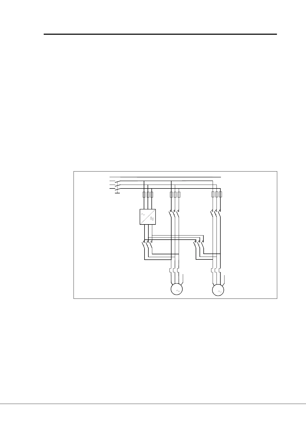
Figure 6-36 Example of two pump autochange, main diagram
PE
L1
L2
L3
UVW
PE
UVW
PE
M1
M2
F1
F2
F3
VACON
UVW
L1 L2 L3
Q1
K1
K2
K1.1
K2.1
M
M
3
3
ac2maint.ds4
 Loading...