Vacon Plc Phone: +358-201 2121 Fax:+358-201 212 205
Service: +358-40-8371 150 E-mail: vacon@vacon.com
E-mail: application.team@vacon.com
Vacon Page 61
Pump control with autochange
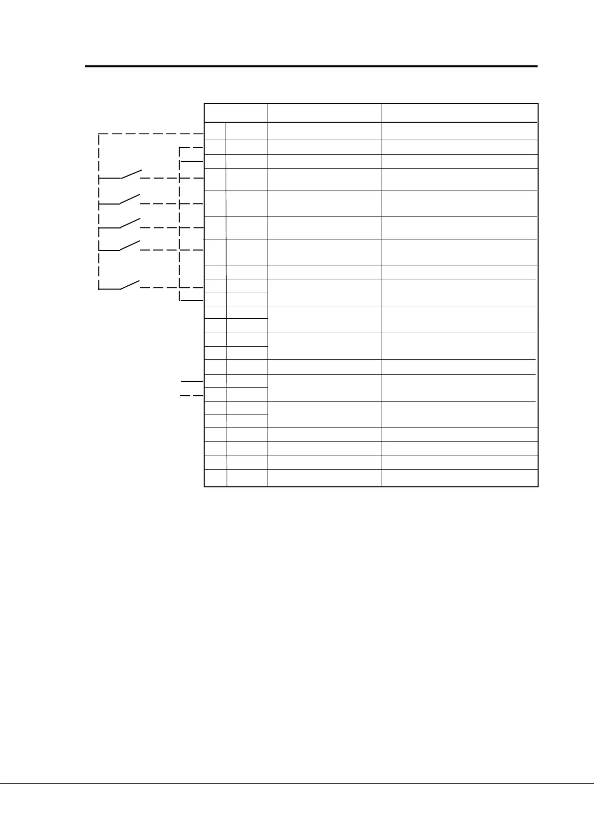
Terminal Signal Description
206 +24V Control voltage output Voltage for switches, etc. max. 0.1 A
207 GND I/O ground Ground for reference and controls
208 COME Common for DIC1-DIC7 Connect to GND or + 24 V
209 DIE1 Interlock input, Contact closed = interlock is active
autochange 1
210 DIE2 Interlock input Contact closed = interlock is active
autochange 2
211 DIE3 Interlock input, Contact closed = interlock is active
autochange 3
212 DIE4 Interlock input Contact closed = interlock is active
autochange 4
213 Not used
214 DIE6A+ Interlock input Contact closed = interlock is active
215 DIE6A- autochange 5
216 DIE7B+
217 DIE7B-
218 DOE1
219 DOE2
220 Not used
221 TI+ Termistor input
222 TI-
225 RO4/1 Aux. drive 3 / autochange 3 control
226 RO4/2
231 DOE3 Open collector output 3 Aux. drive 1 / autochange 1 control
232 GND I/O ground
233 DOE4 Open collector output 4 Aux. drive 2 / autochange 2 control
234 GND I/O ground
Figure 7-2 I/O-Expander 202OPT with pump and fan control (Profibus)
Signal from
motor termistor
NOTE! Termistor input (terminals 327 and 328) must be shorted if not used.
READY = ON, when mains voltage has been applied and Vacon CX is ready to operate.
RUN = ON, when motor is running.
FAULT = ON, if a fault occurs.
FIELDBUS CONTROL = ON, when the fieldbus board is the Active Control Source.

 Loading...


