Vacon Plc Phone: +358-201 2121 Fax:+358-201 212 205
Service: +358-40-8371 150 E-mail: vacon@vacon.com
Page 62 Vacon
Pump and fan control with autochange
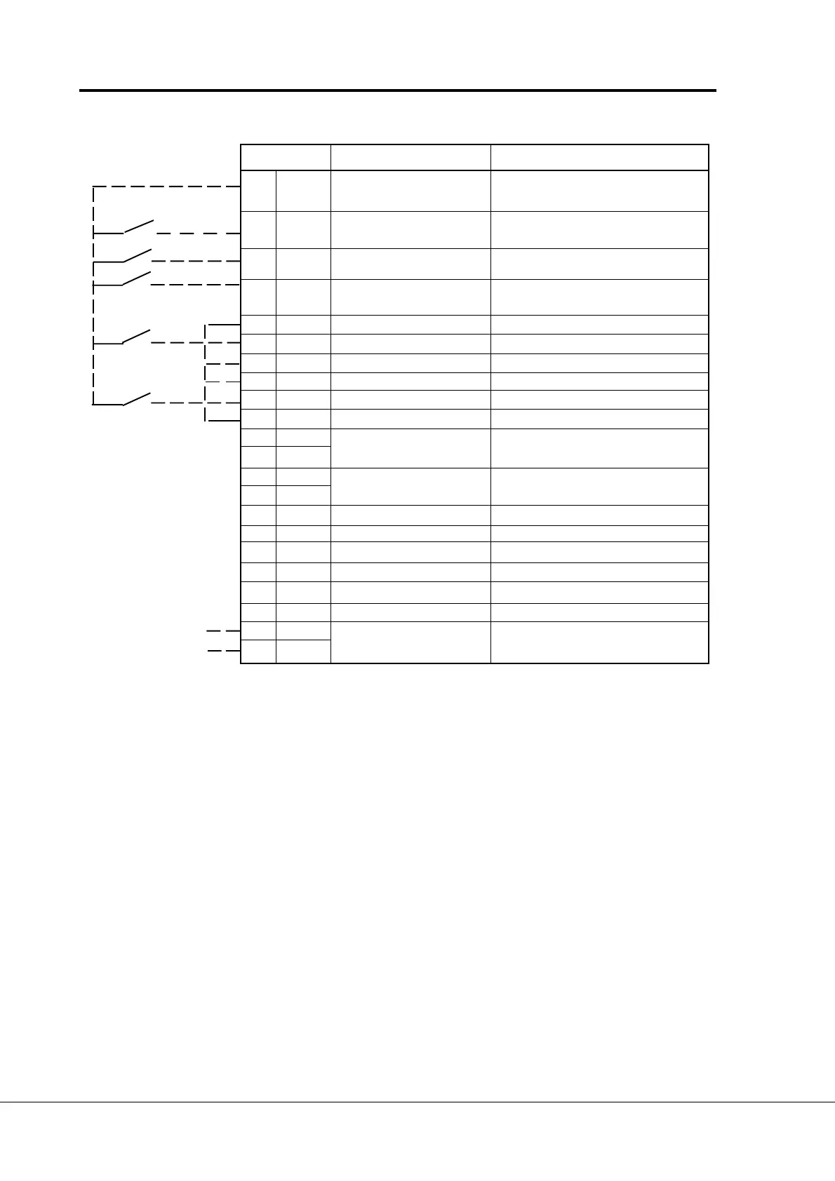
Terminal Signal Description
301 DID1 Interlock input, Contact closed = interlock is active
autochange 1
302 DID2 Interlock input Contact closed = interlock is active
autochange 2
303 DIE3 Interlock input, Contact closed = interlock is active
autochange 3
304 DIE4 Interlock input Contact closed = interlock is active
autochange 4
305 COMD Common for DID1-DID2 Connect to GND or +24 V
306 +24 V Control voltage output Voltage for switches, etc. max. 0.1 A
307 COME Common for DIE3-DIE4 Connect to GND or +24 V
308 GND I/O ground Ground for reference and controls
309 DID5A+ Interlock input Contact closed = interlock is active
310 DID5A- autochange 5
311 DID6B+
312 DID6B-
313 DID7Z+
314 DID7Z-
315 GND I/O ground Ground for reference and controls
316 DOD1 Open collector output 1 Aux. drive 1 / autochange 1 control
317 DOD2 Open collector output 2 Aux. drive 2 / autochange 2 control
318 DOD3 Open collector output 3 Aux. drive 3 / autochange 3 control
319 DOD4 Open collector output 4 Fieldbus control
320 GND I/O ground Ground for reference and controls
327 TI+ Termistor input
328 TI-
Figure 7-3 I/O-Expander 201OPT with pump and fan control (Modbus)
NOTE! Termistor input (terminals 327 and 328) must be shorted if not used.
READY = ON, when mains voltage has been applied and Vacon CX is ready to operate.
RUN = ON, when motor is running.
FAULT = ON, if a fault occurs.
Signal from
motor termistor

 Loading...


