Seite 37 von 72 // page 37 of 72
Das Dokument darf nur vollständig und unverändert verwendet und weitergegeben werden. Es liegt in der Verantwortung des
Anwenders, die Gültigkeit dieses Dokumentes bezüglich seines Produktes sicher zu stellen.
Documents are only to be used and distributed completely and unchanged. It is strictly the users´ responsibility to check carefully
the validity of this document with respect to his product.
Cleaning parts
- Check through bores of the oil lines, clean if necessary.
- Check all seal rings for conglutination and cracks, replace if necessary.
- Check silencer nozzle, clean if necessary.
- Remove threaded plug of the detent ball in the bearing cover. Remove and check detent ball with
spring, replace if necessary.
- Remove oil separator upper and lower part.
- Check valve cap, spring and valve seat. Replace valve cap and spring if necessary.
Changing the coupling bushes
- Check coupling bushes in the rotors, replace if necessary.
- Remove bushes, e. g. by using a small woodscrew. Press in flush new coupling bushes.
Changing the shaft seals
- Check shaft seals in the bearing plate, intermediate bearing plate and bearing cover and replace if
necessary.
- Remove shaft seal from housing by using an appropriate mandrel (special tool, see below).
- Press in new shaft seal, make sure that it remains level to bore.
- Assemble shaft seals only by using a special mandrel (see below). Apply pressure only to the outer
ring. Take into consideration that the mandrel will pass under the seal and ensure that no other part
can be damaged.
Assembly of the pump
- Assemble pump in reverse order of disassembling.
- Check that seals are correctly seated, fix with vacuum grease if necessary.
- Coat all wear faces with pump oil.
- Replace damaged parts and defective seals.
- Check that O-rings are in perfect condition.
- If installing new O-rings, stretch slightly to seat, use vacuum grease if necessary.
- Place oil pump rotor with rounded face first in bearing cover.
- Fill in vacuum oil into the oil pump before assembling oil pump vanes.
- Position oil pump cover so that the internal half-round groove is directed right to the detent ball.
- Position the complete assembled pump unit in the oil reservoir and screw together with housing.
- Assemble removable sleeve.
- Fill half of the chamber in front of the removable sleeve with pump oil.
- Position shielding with O-ring.
- Press in the coupling until limit stop using a rubber mallet (do not damage parts e. g. motor shaft).
- Screw in the grub screw to the coupling element.
- Position the cover plate
- Assemble the intermediate flange.
- Assemble the motor.
- Assemble the hose cover.
- Assemble the connecting hoses.
- Assemble separator and oil mist filter.
- Fill in pump oil (see ”Oil change” in the instruction for use).
- Allow the pump to run with gas ballast valve open and inlet closed for approx. 1 h.
Note: Replacing the motor is only possible at the factory. Special tools are necessary.
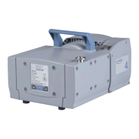
Checking the diaphragm pump is described in the instructions for use for the RC 5.