Seite 64 von 72 // page 64 of 72
Das Dokument darf nur vollständig und unverändert verwendet und weitergegeben werden. Es liegt in der Verantwortung des
Anwenders, die Gültigkeit dieses Dokumentes bezüglich seines Produktes sicher zu stellen.
Documents are only to be used and distributed completely and unchanged. It is strictly the users´ responsibility to check carefully
the validity of this document with respect to his product.
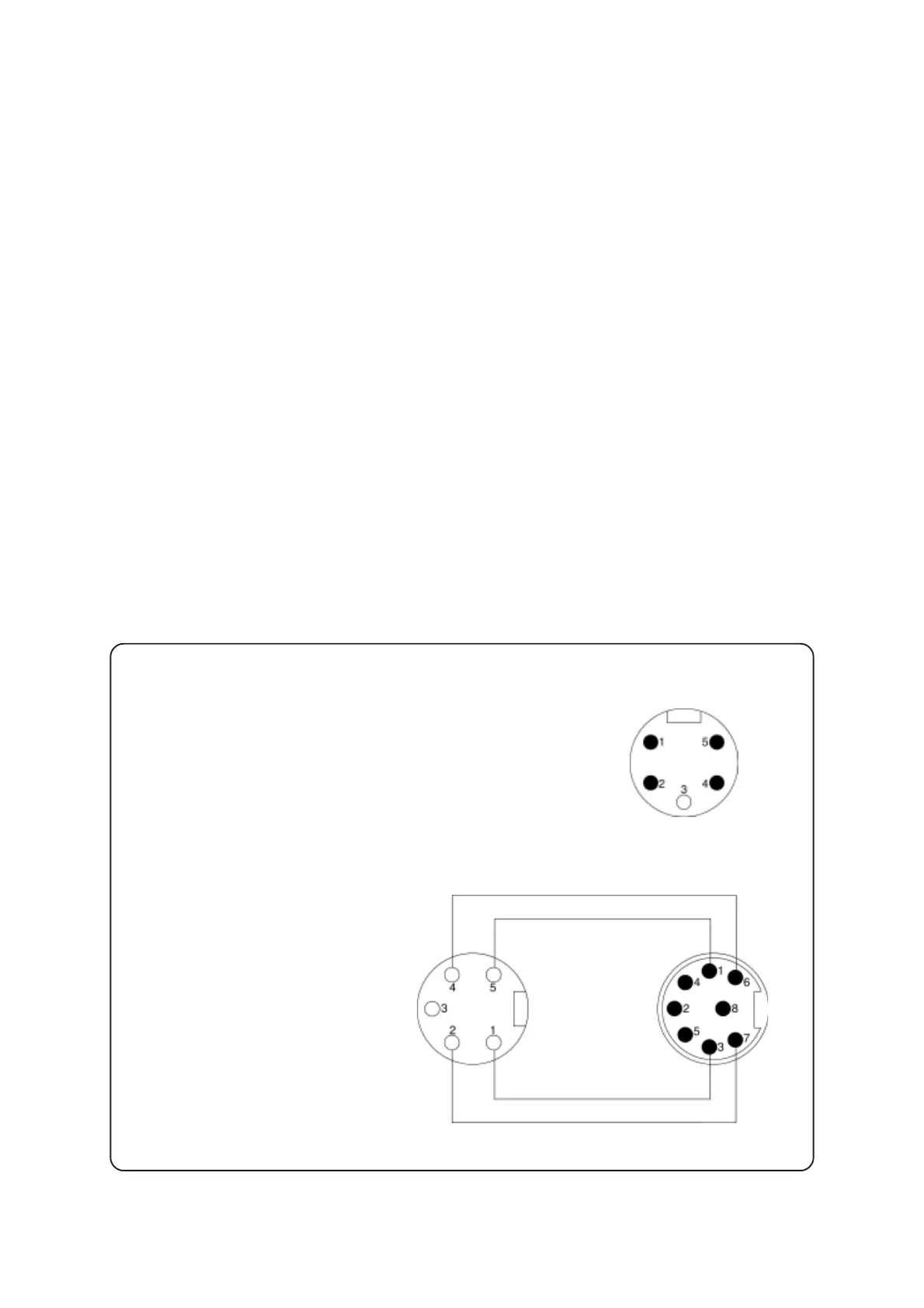
Checking the gauge head VSP 5:
Resistance of the filament: approx. 85 Ω
at ambient temperature (between pins 2 and 4).
Checking connecting cable:
Check wiring continuity.
Connector gauge head side
Sensor plug
Connector instrument
side
Replacing the EPROM
➨ Remove the defective EPROM (note correct position) and replace it by a new one.
Replacing the plug-in LCD
➨ Unscrew the four Phillips screws and remove the defective read out pcb from the front side of the
housing.
➨ Unplug the defective LCD from the pcb and assemble the new LCD, make sure that the mark at the
LCD is at the side of the VACUUBRAND logo on the read out pcb. When assembling the LCD, only
exert pressure to the side with the pins of the LCD.
➨ Screw together the read out pcb with LCD and the housing front part.
Replacing the component group housing front part with glass pane and read out
pcb with plug-in LCD (for controllers without plug-in LCD)
➨ Remove defective component group by a new one.
Replacing the component group housing front part with glass pane (for control-
lers with plug-in LCD)
➨ Unscrew the four Phillips screws and remove the read out pcb together with the plug-in LCD.
➨ Assemble the read out pcb with LCD to the new housing front part with glass pane.
 Loading...