5
The device should be operated by trained technicians, mentally and physically able to operate the
vacuum set and its components.
Vacuum set is intended for professional use. It is not intended for non-professional use. The buyer is
obligated to secure the vacuum set and all its components against unauthorized use.
Do not use the device or any of its parts for purposes other than those for which it was intended. Do not make any
modifications or changes to the vacuum set or its components. Any modifications or changes are made by the customer
under his sole responsibility and will void the warranty.
Vacuum sets are used in the process of degassing casting materials such as silicone, resin, gypsum and the process of
impregnation of wood and other porous materials.
The vacuum chamber is a sealed tank. Inside it is possible to create a low-pressure environment by sucking out gases
contained therein by the vacuum pump.
The vacuum set is operated in the following conditions: ambient temperature between +5°C and +40°C, air humidity up to
80% at 20°C.
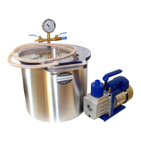
Photo 1: Vacuum set.
The vacuum set (Photo 1) consists of a vacuum chamber (2) and a vacuum pump (3) connected by a pneumatic hose (1). The
properties of the Vacuum Chamber are described in the next section of this manual. The vacuum pump included in the standard
vacuum set is a rotary oil pump. In the vacuum set, instead of a rotary oil pump, an oil-free piston pump or a diaphragm pump
can be used. This manual describes the installation of a vacuum set which includes an oil rotary pump. In case of using a
different type of pump or a pump supplied by another manufacturer, read and follow the instructions provided with the pump.
VcuumChambers.eu is not responsible for vacuum pumps provided by other manufacturers or distributors. The vacuum hose
included in the set is a reinforced pneumatic hose with a fitting enabling connection to a vacuum pump. The vacuum set is also
equipped with the oil necessary to start the pump for the first time (when using a rotary oil pump) and the user manual.
The vacuum set can be equipped with additional elements: a fitting muffler, a stirrer mechanism, a vacuum trap or a
vacuum feedthrough with a pouring hose and mechanical flow controller. These elements are described in chapter "5.
Additional equipment. " of this manual.
The vacuum chambers used in vacuum sets vary in size and material. Photo 2 shows an example of a vacuum chamber. The
vacuum chamber tank, depending on its type is made of aluminium, powder-coated steel or stainless steel. The lid of the
chamber is made of thick polycarbonate or tempered glass. The tank is provided with a silicone gasket which is durable and has
a low susceptibility to mechanical deformation. Excellent transparency of the lid allows observation of the degassing process.
1
2
3
6
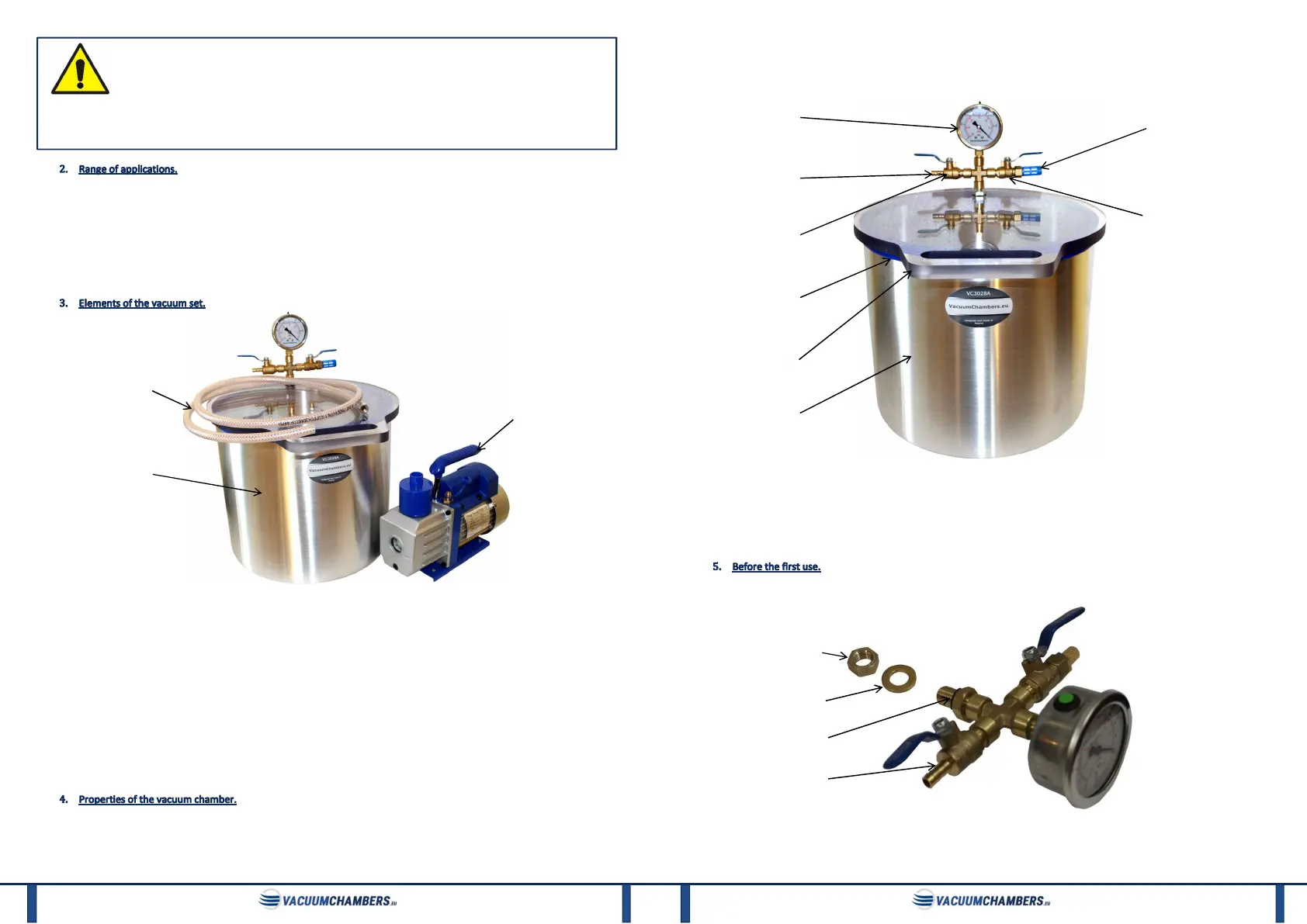
The two ball valves allow for adjusting the degassing process, and the mounted vacuum gauge indicates the current vacuum in
the chamber. The chamber is equipped with an inlet air filter, which effectively prevents dirt from getting into a degassing
material. The chamber is attached to the pump with a barb, on which is fitted a reinforced hose with an internal diameter of 8
mm and a length of 1.5 m. The whole product is made from materials of the highest quality and a branded thread sealant.
Photo 2: Vacuum chamber.
Elements 1 to 5 together with pneumatic fittings form an air manifold. It also includes the washer and nut needed for its
assembly. The manifold is mounted on a tank or lid, but due to the risk of damage during transport, it can be attached to the
vacuum set separately. In that case, the customer should mount the manifold on the tank or lid by following the instructions in
this manual.
A. Air manifold assembly.
Photo 3: Air manifold.
If the air manifold (Photo 3) is supplied separately, unpack it and take off the nut and washer. Do not remove the O-ring.
The pneumatic fitting, from which the nut and the washer were removed, should be placed in the hole, prepared by the
1
2
nut
washer
O-ring
air manifold
3
4
7
8
6
2. Barb fitting for 8mm hose.
3. Exhaust air valve.
4. Silicone gasket.
5. Lid.
6. Tank.
7. Air filter.
8. Intake air valve.
 Loading...