9
Depending on the selected model or on the customer's order, the vacuum set can be equipped with: a fitting muffler, stirrer
mechanism, vacuum trap or vacuum feedthrough with a pouring hose and mechanical flow controller.
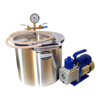
A. Fitting muffler.
Photo 9: Fitting muffler and air manifold with a mounted muffler.
The fitting muffler (Photo 9) disperses the air stream entering into the chamber, while balancing the vacuum. It prevents
casting materials from spilling inside the chamber. This accessory should be screwed manually (not using any tools) onto the
mounted air manifold on the internal side of the tank or the bottom side of the lid. The diffuser is not included as a standard
accessory with every vacuum set.
B. Vacuum feedthrough with pouring hose and mechanical flow controller.
The feedthrough integrated with the vacuum chamber (Photo 10) enables to supply of casting materials from the external
container directly into the interior of the chamber under vacuum. The mechanical flow controller (4), included in the set, allows
for precise process control. To regulate the process of collecting material into the chamber, operate the wingnut located on the
regulator. It allows for reduce or block pouring hose capacity.
When using the vacuum set, the pouring hose becomes dirty with the supplied materials. This situation is normal
operational wear and is not covered by warranty. The customer is obliged to replace a dirty hose each time, following the
instructions below.
To remove the hose from the vacuum feedthrough (1), loosen the nut (2) with a spanner. The hose should be at ease
removed from the feedthrough. The next step is to remove the flow regulator (4) from the hose after loosening the wing head
screw.
Put the mechanical flow regulator (Photo 11) on the new hose. The hose should be centrally located under the regulator
stamp, between the stamp and the opposite wall. Tighten the regulator with the wing head screw as needed.
Photo 10: Vacuum feedthrough with pouring hose and flow controller mounted on the tank.
1
2
3
4
10
Photo 11: Mechanical flow controller.
The spare end of the hose should be placed in the vacuum feedthrough (Photo 10). A sufficiently long section of the hose
should be inside the tank. Use one spanner to tighten the feedthrough nut and another spanner to hold the feedthrough.
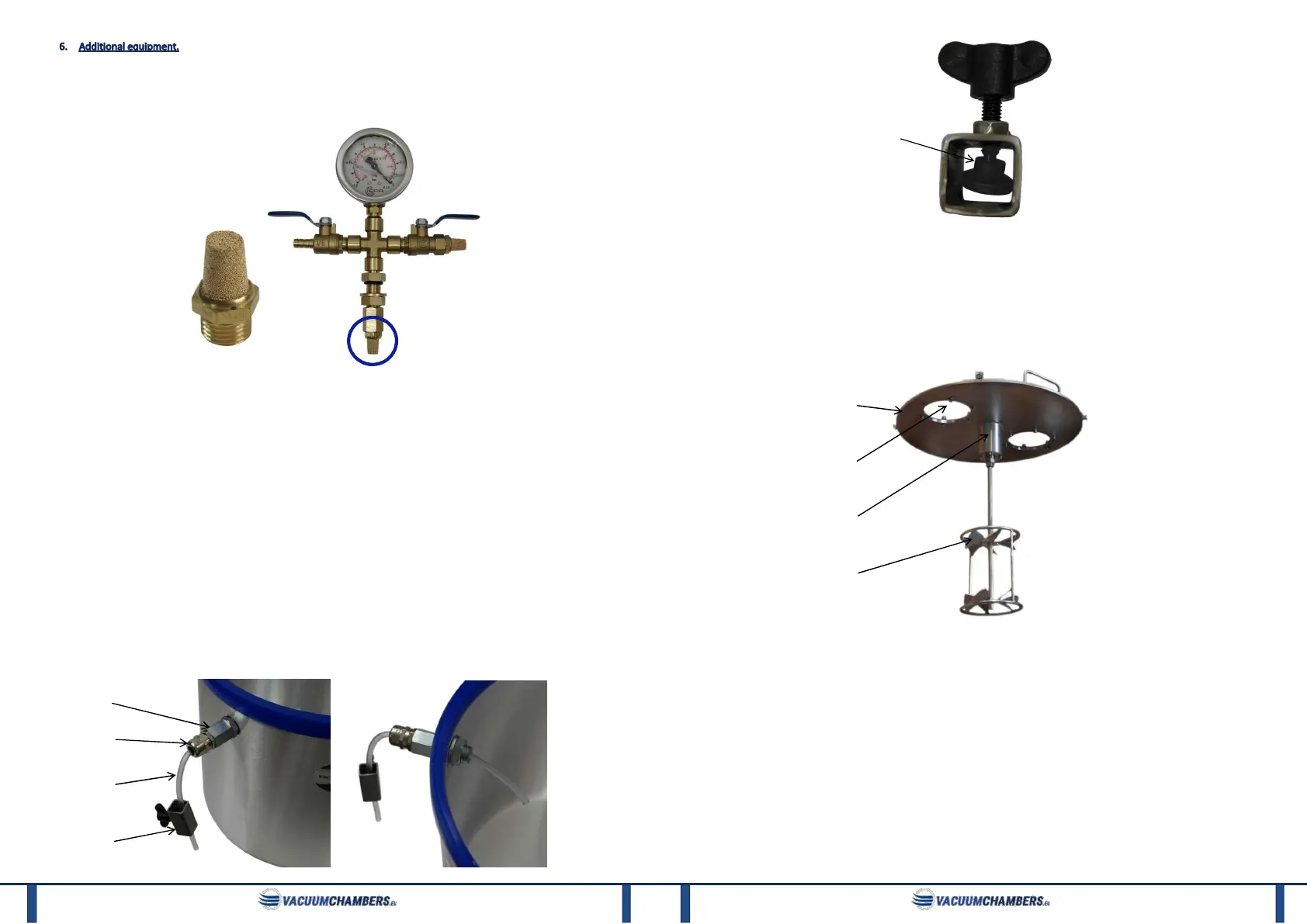
C. Stirrer mechanism.
The stirrer mechanism is an additional accessory of the vacuum chamber. It facilitates and speeds up the degassing process.
The stirrer mechanism can only be installed in the chamber suitable for this. During operation, the stirrer must not move faster
than 300 rpm. Photo 12 shows the chamber lid (1) with the agitator (4) attached to it.
Photo 12: Agitator mounted on the lid.
The agitator is ended with an ISO metric screw thread (M14), which allows it to be screwed into the coupling (3). This
connection is secured with a lock nut. The coupling has a hole on the upper side of the lid to which the agitator drive can be
connected. The hole also has an M14 thread. A bolt with a nut may be inserted therein. The lid of the vacuum chamber with the
stirrer mechanism additionally has two polycarbonate windows (2), which enable the observation of the degassing process. They
are secured during transport with a protective foil.
The chamber adapted to the installation of the stirrer mechanism (Photo 13) has a metal lid (1) and additional elements.
Those are:
stamp
1
2
3
 Loading...