7
manufacturer. Depending on the model of the vacuum chamber, the hole is located in the wall of the tank or the lid of the
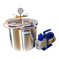
vacuum chamber. The manifold should be located on the outside of the chamber (Photo 4) or on the top of the lid (Photo 2).
Photo 4: Air manifold inserted into the hole.
The washer and nut should be placed on the manifold fitting on the internal side of the tank or bottom side of the lid.
Smooth washer edges should touch the tank wall (or lid wall). Use one spanner to tighten the connection and the other spanner
(or your hand) to hold the fitting. Tighten the nut until you feel resistance. It is important to place the O-ring and the nut
concentric. Incorrect positioning may result in a lack of tightness in the chamber. Photo 5 shows the incorrect position of the
sealing ring. Do not tighten the O-ring too hard or you will deform it and damage its properties.
Photo 5: Incorrect position of the O-ring.
Photo 6: Air manifold correctly installed.
Photo 6 shows a correctly mounted air manifold on the tank wall. The green stopper plug, visible in the photo, is used to
protect the vacuum gauge against spilling glycerine during transport or assembly. It should be removed after all components of
the vacuum set have been assembled. Leaving the stopper plug in the vacuum gauge may result in incorrect pressure
indications.
O-ring
washer and nut
8
B. Preparation of the vacuum pump.
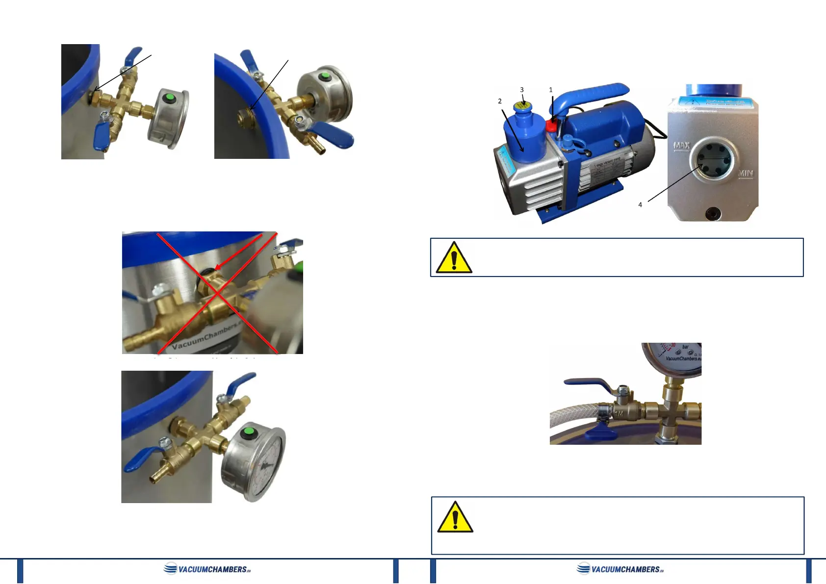
1) Before the first use necessarily fill the vacuum pump (Photo 7) with the oil provided with the set. To do that, place the
pump on the flat, horizontal surface, unscrew the red plug (1) and pour the oil through the oil feed hole. For some models of
pumps (when there is no red cap), the oil should be poured through the hole in the pump housing, after the blue oil filter
cylinder (2) has been unscrewed. Oil pour gradually, at the same time control the oil level by observing the oil sight glass (4).
Photo 7: Elements of the vacuum pump and correct oil level.
The pump delivered to the client is never filled with oil. A little amount of oil in the oil sight glass indicates only
the fact that the pump was tested before the shipment. The pump must necessarily be filled with oil before
use.
2) Remove the plug (3), protecting the air filter, placed on the exhaust of the vacuum pump. Not applicable to the VP1RS-
0.5 model.
C. Connection of elements of the vacuum set.
1) Screw the connector, tighten the pneumatic hose, to the vertical fitting on the vacuum pump. Screw the connector
gently, using a spanner, until the resistance is felt.
Photo 8: Pneumatic hose mounted on the barb of the ball valve, secured with worm drive hose clamp.
2) Put the spare end of the pneumatic hose on the barb of the chamber ball valve. Secure this connection using a worm
drive hose clamp.
3) Remove the green plug of the rubber plug on the vacuum gauge.
It is recommended to connect the vacuum set only with parts and products supplied by VacuumChambers.eu.
If the customer connects the vacuum set or its parts with elements or devices from other manufacturers, the
customer is solely responsible for the appropriate selection of these elements, their compatibility and the
quality of their connection. The manufacturer is not responsible for any damage or losses caused by incorrect
selection, matching, use or combination of the products. The above principles apply in particular to vacuum pumps purchased
from other suppliers.
 Loading...