The safety valve discharge pipe must be routed to outside the building, must not discharge
above an entrance or window or any type of public access area, be clear of any electrical fittings
and positioned so that any discharge can be seen.
3.18.2 Expansion vessel
A diaphragm type expansion vessel, conforming to the current issue of BS4814 (see also
BS7074 Part 1 and 2). For IE the current edition of IS 813, must be connected at a point close
to the inlet side of the circulating pump, see the Typical installation, Fig. 3.10. unless laid down
differently by the manufacturer.
The expansion vessel volume depends on the total water system volume and the initial system
design pressure. For any system an accurate calculation of vessel size is given in the current
issue of BS5449 and BS7074 Part 1.
Example: For an initial design pressure of 0.7 bar, the minimum total vessel volume required is
0.063 × Total System Volume.
NOTE:
A higher initial design pressure requires a larger volume expansion vessel.
The charge pressure must not be less than the static head of the system, that is, the height of
the highest point of the system above the expansion vessel.
3.18.3 Pressure gauge
A pressure gauge with a set pointer and covering at least 0 to 4 bar (0 to 60 lb/in2) shall be
fitted permanently to the system in a position where it can be seen when filling the system.
3.18.4 Water make up
Provision should be made for replacing water loss from the system using a make up bottle
mounted in a position higher than the top point of the system, connected through a non-return
valve to the return side of either the heating circuit or the hot water cylinder.
Alternatively, provision for make up water should be made using a proprietary filling loop.
3.18.5 Filling a sealed water system
Provision for filling the system at low level must be made. This can be achieved by the use of a
proprietary filling loop.
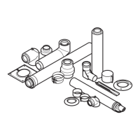
Fig. 3.10 Typical installation