Supplied By www.heating spares.co Tel. 0161 620 6677
49
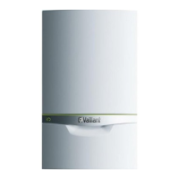
INSTALLATION OF THE HORIZONTAL AIR/FLUE DUCT Ø 80/125 WITH
EXTENSIONS
• Taking each extension to be used,
fit the flue duct into the air duct
and secure using the 3 screws
provided.
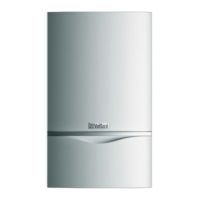
• For ease of measuring and
marking the air/flue duct
extensions, assemble them loosely
together with the air/flue duct and
terminal assembly as shown
(fig. 4.6).
Note: The joints between the flue duct
sections are of a push-fit type, with
the flue duct spigot inserted into a
socket containing a sealing ring. For
ease of installation lubricate the seal
using soap solution prior to
assembling.
• Assemble the flue such that there
is a gap of about 10 mm between
each air duct, which will ensure
the correct flue duct penetration
into the flue sockets of 30 mm.
All flue sockets should point
towards the flue terminal.
• Measure from the flue terminal
and mark the air duct to a length
of:
Dimension A + 60 mm
• Take the extension(s) to be
shortened and remove the
3 screws. Separate the ducts.
Note: For assembly reasons do not
shorten any air duct to a length of
less than 100 mm. If necessary
shorten two adjacent extensions to
achieve the overall required length.
• Cut the air duct square and
remove any burrs.
• Refit the flue duct into the air duct
and secure using the 3 screws.
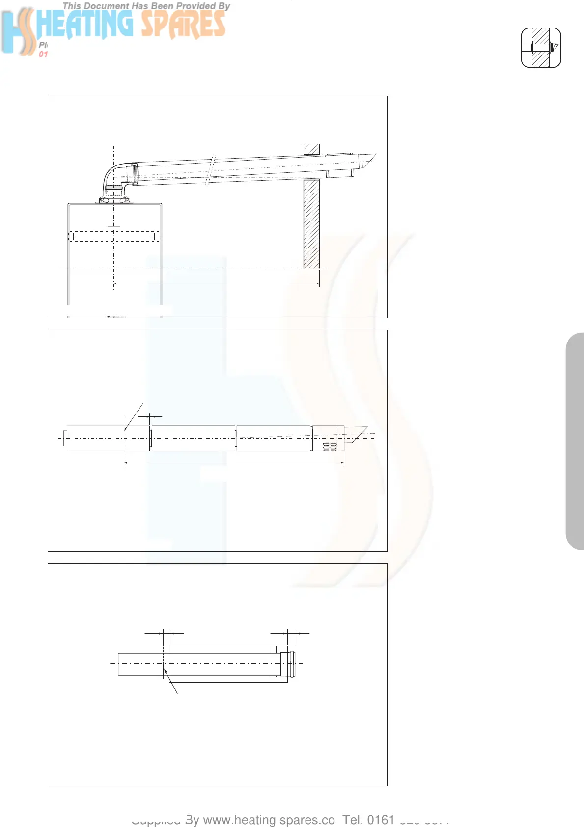
• Cut the flue duct as detailed in
fig. 4.7.
• When cutting the air and flue
ducts it is important to remove any
burrs with a file, this ensures easy
fitting of the ducts and prevents
any rough edges from damaging
the flue seals.
• Care should be taken not to
scratch the white surface of the air
duct.
• If the installation requires the use
of air/flue duct extensions,
additional bends or elbows refer
to the sections on pages 55 - 59.
• At this stage it is necessary to
prepare and fit the boiler onto the
hanging bracket – refer to the
boiler installation instructions.
• Fit the appliance flue outlet
adaptor to the boiler.
Fig. 4.5
LAS Euro B/S 082/0
10 mm
Mark air duct here
Dimension A + 20 mm
Fig. 4.6
LAS Euro B/S 084/0
25 mm
Mark flue duct here
15 mm
Fig. 4.7
LAS Euro B/S 080/0
Dimension A + 60 mm
PART 2 CONCENTRIC 80/125
834449_09GB_082006.qxd 10.08.2006 12:20 Seite 49
 Loading...