10 Air/flue pipe installation manual 0020308120_02
4 System conditions
4.1 Technical properties of the air/flue systems
from Vaillant for condensing products
Technical feature Description
Temperature resistance Adapted to the maximum
flue gas temperature of the
product.
Leak-tightness Adapted to the product for use
in buildings and outdoors.
A leak-tightness test must be
carried out at a test pressure
of 200 Pa. At a diameter of
50 mm, a test pressure of
1500 Pa must be used for the
test.
Condensate resistance For gas and oil fuels
Corrosion resistance Adapted to the gas and oil
condensing boiler
Clearance from combustible
materials
– Concentric air/flue pipe-
work: No clearance re-
quired
Installation site In accordance with the install-
ation instructions
Resistance to fire Normal level of flame resist-
ance (in accordance with EN
13501-1 Class E)
Fire resistance duration None:
The external pipe of the con-
centric air/flue pipe are not
flammable. A required fire res-
istance duration is provided by
shafts within the building.
4.2 Route of the air/flue pipe in buildings
The air/flue pipe should be as short as possible and run as
straight as possible.
▶ Do not arrange several elbows or inspection elements
immediately after each other.
As a result of standards relating to the hygiene of potable
water, potable water lines must be protected against imper-
missible heating.
▶ Lay the air/flue pipe separately from the potable water
lines.
It must be possible to check and, if required, clean the entire
length of the flue gas route.
It should be possible to remove the air/flue pipe again with a
minimal amount of effort (preferably no time-consuming mor-
tising work in the living area, but screwed-in casing instead).
If they are arranged in shafts, they are usually easy to re-
move.
4.3 Location of the terminal
The location of the flue system terminal must comply with
the relevant applicable international, national and/or local
regulations.
▶ Align the terminal of the flue system in such a way that
ensures a secure outward flow and distribution of the
flue gases and prevents these gases from re-entering the
building through openings (windows, supply air openings
and balconies).
▶ Observe the existing regulations with regard to the clear-
ances to windows and ventilation openings.
4.4 Disposing of condensate
▶ When disposing of the condensate into the public waste-
water system, observe the local regulations.
▶ Use only corrosion-resistant piping material for the con-
densate discharge pipe.
4.5 Clearance between combustible materials
and the components
On individually connected products, it is not necessary to
leave any clearance between the concentric air/flue pipe
and/or the corresponding extension and components made
from combustible materials.
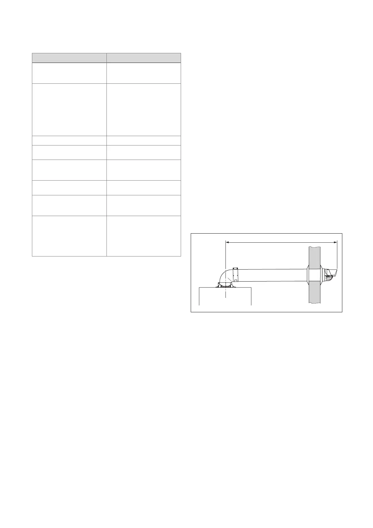
4.6 Maximum pipe lengths
4.6.1 Maximum pipe length for horizontal wall duct
A Maximum pipe length

 Loading...


