Appendix
26 Installation and maintenance instructions eloBLOCK 0020265768_01
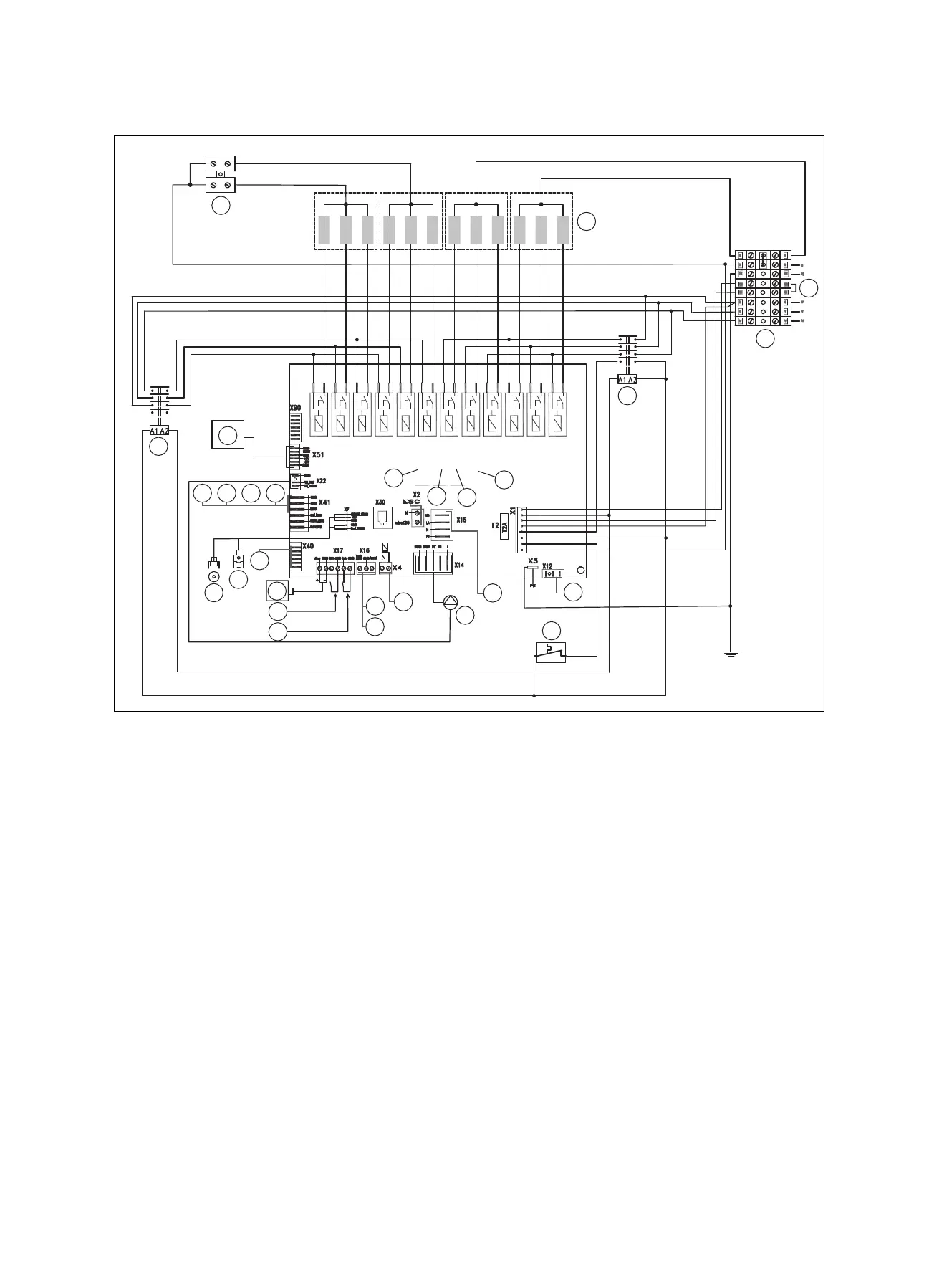
F.3 VE24 /14 EU I, VE28 /14 EU I wiring diagram
1
2
4
5
12
11
13
10
9
7
8
6
14
15
16
17
18
19
22
21
20
28
27
3
23242526
1 Connection terminal N
2 24 kW (4 x 6 kW), 28 kW (4 x 7 kW) immersion
heaters
3 Limit thermostat for underfloor heating (remove the
bridge when connecting)
4 Power supply – main connection block
5 Contactor 1
6 Power supply for external VR 40 module
7 Safety cut-out
8 Heating pump
9 Connection for 3-port diverter valve
10 RE 14 – relay for heating pump
11 RE 15 – 3-port diverter valve
12 RE 16 – relay for contactor
13 RE 13 – relay for two-stage pump (non-EU)
14 Cascade connection
15 Cylinder temperature sensor
16 Cylinder thermostat
17 Output limiter
18 Room temperature control
19 eBUS connection
20 Pressure sensor
21 Temperature sensor
22 Signal connection for external VR 40 module
23 DCF 77
24 System temperature sensor
25 Outdoor temperature sensor
26 Circulation pump remote control
27 Contactor 2
28 User interface connection
 Loading...