Electrical installation 6
0020291544_01 Hydraulic Station Installation and maintenance instructions 29
6.5 Establishing the power supply, 1~/230V
▶ Determine the type of connection:
Case Connection type
Energy supply company lockout not
provided
Single power supply
Energy supply company lockout
provided, shutdown via connection
S21
Energy supply company lockout
provided, shutdown via partition
Dual power supply
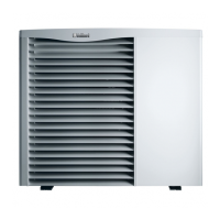
6.5.1 1~/230V single power supply
1
2
3
4
5
6
L1
L1
L2
L3
N
X300X310X311
2
1
L1
N
3
4
1
2
N
L
N
L
1. Note the specifications on the sticker on the electronics
box.
2. Install a disconnector for the product.
3. Use the preinstalled 3-pole power supply cable (3 x
4 mm
2
).
4. Connect the power supply cable to L1, N, PE.
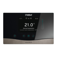
6.5.2 1~/230V dual power supply
1
2
3
4
5
6
L1
L1
L2
L3
N
X300X310
X311
2
1
L1
N
3
4
1
2
N
L
N
L
N
L
1. Note the specifications on the sticker on the electronics
box.
2. Install two disconnectors for the product.
3. Use the preinstalled 3-pole power supply cable and an
additional 3-pole power supply cable (3 x 4 mm
2
) with a
temperature resistance of 90 °C.
– Note that commercially available power supply
cables do not usually have sufficient temperature
resistance.
4. Connect the preinstalled power supply cable to the
X300 connection with the heat pump electricity meter.
5. Remove the 2-pole bridge between the X310 and X311
connections.
6. Connect the additional power supply cable (from the
household electricity meter) to the X311 connection.
7. Use the strain relief clamps to secure the cables in
place.
6.6 Establishing the power supply, 3~/400V
▶ Determine the type of connection:
Case Connection type
Energy supply company lockout not
provided
Single power supply
Energy supply company lockout
provided, shutdown via connection
S21
Energy supply company lockout
provided, shutdown via partition
Dual power supply
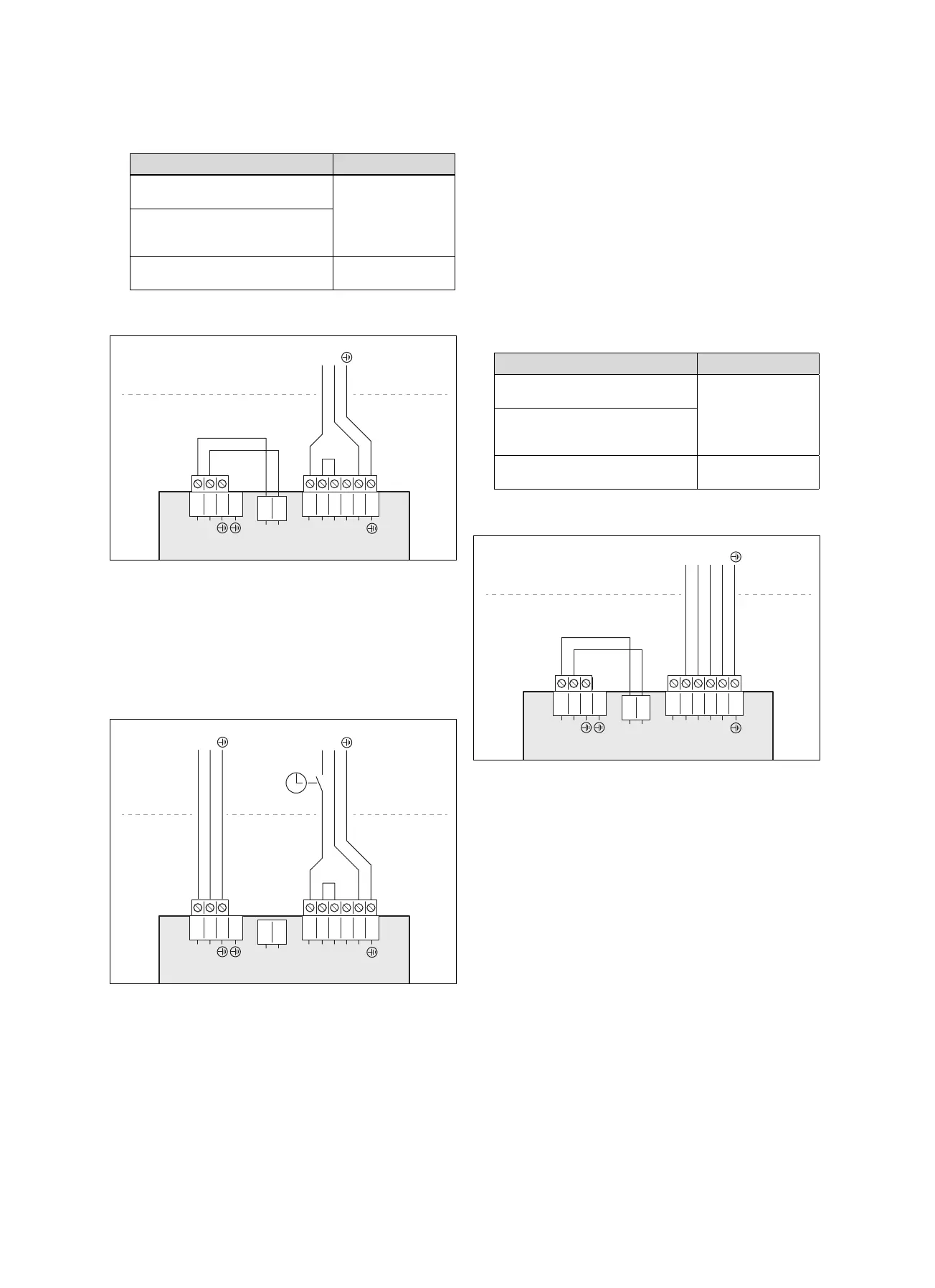
6.6.1 3~/400V single power supply
1
2
3
4
5
6
L1
L1
L2
L3
N
L1
L2
L3
N
X300X310X311
2
1
L1
N
3
4
1
2
N
L
L
1. Note the specifications on the sticker on the electronics
box.
2. Install a disconnector for the product.
3. Use the enclosed 5-pole power supply cable (5 x
2.5 mm
2
) .
4. Remove the preinstalled 3-pole power supply cable to
the X300 connection.
5. Remove the 2-pole bridge between contacts L1 and L2
on the X300 connection.
6. Connect the 5-pole power supply cable to the X300
connection.
 Loading...