39
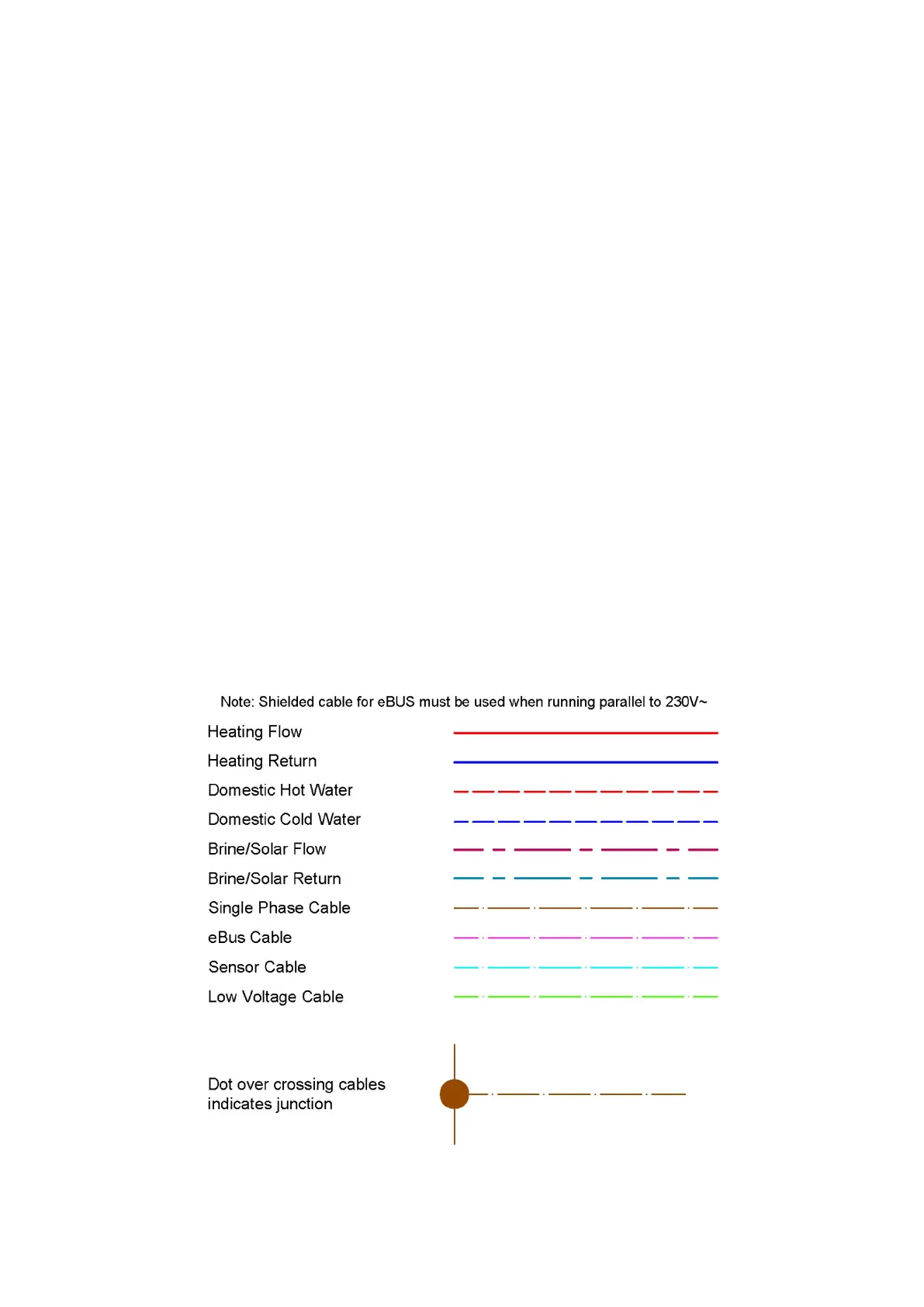
Schematics Legend
01 Boiler
05 DHW Cylinder
08 Inlet Safety Group
12 Internet Gateway (VR 920)
13a Wiring Centre (VR 71)
13b Wiring Centre (VR 70)
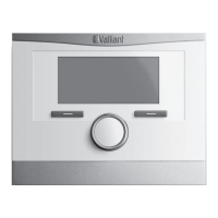
13d Zone Controller - Wireless (VR 91f)
13d Zone Controller (VR 91)
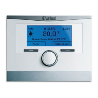
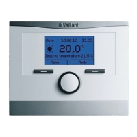
13e System Controller - Wireless (VRC 700f)
13e System Controller (VRC 700)
13f Wireless Reciever
16 Outdoor Temperature Sensor
19 High Limit Thermostat
23 Immersion Heater
25 Solar Pump Station
30 Non-return Valve
32 Expansion Vessel Service Valve
33 Y-Strainer
36 Zone Valve
39 Thermostatic Mixing Valve
42b Domestic Expansion Vessel
42c Heating Expansion Vessel
50 Automatic Bypass Valve
57 Brine Expansion Vessel
59 Solar Air Seperator
63 Solar Collector
64 Solar Protection Vessel
65 Glycol Catch Tank
67 Electronic Mixing Valve
73 Magnetic System Filter
87 Isolation Valve
88 General Pump
95 Legionella Protection Pump
 Loading...