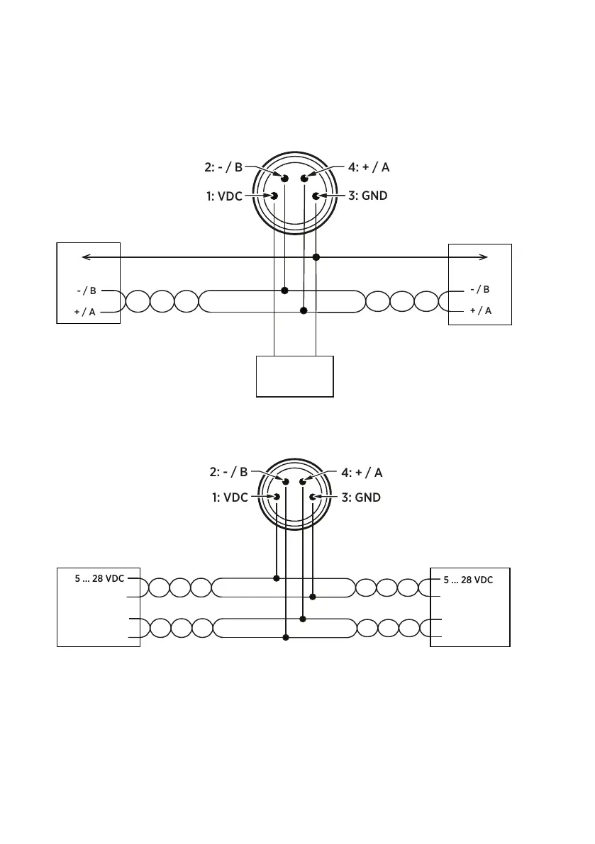
The following figures show the recommended wiring when connecting multiple devices to the
RS-485 interface using either a separate local power supply for each device or a common
power supply.
HMP60/HMP110 M8 CONNECTOR
5 ... 28 VDC
POWER SUPPLY
TO NEXT DEVICE
Figure 14 Wiring multiple devices using local power supply
HMP60/HMP110 M8 CONNECTOR
Figure 15 Wiring multiple devices using common power supply
3.3.2 Wiring with the loop power converter
To use the loop power converter module with an HMP60 or HMP110 series probe, the probe
must be in the analog output mode. The desired parameter is on channel 1, which must be
scaled to 0 ... 2.5 V.
HMP60 and HMP110 Series User Guide M211060EN-J
26

 Loading...