3.3 Connecting the Anemometer
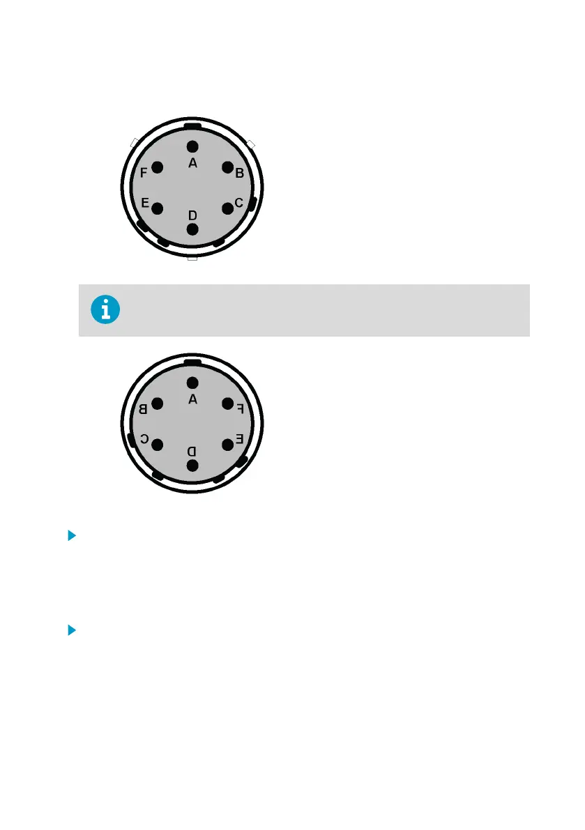
Figure 3 WAA151 Connector Sensor Side
A F+, power input from 9.5 to 15.5 VDC
B GND, common ground
C Fout, signal output
D HTNG, 20 VDC or VAC
E HTNG, 20 VDC or VAC
F Not connected
Vaisala recommends using the SOURIAU UTS6JC10E6P cable connector for the
cable side of this sensor.
Figure 4 WAA151 Connector Cable Side
1. Connect the heating element in the shaft tunnel between pins D and E.
2. Supply the heating element with 20 VDC or VAC.
3.4
Verifying Installation
1. Make sure that the sensor is powered up and connected to the data collection system.
2. Rotate the cup wheel manually and make sure the speed readings change.
Chapter 3 – Installation
11

 Loading...


