1. Open the cup wheel fixing screw with a 2-mm Allen key. Remove the cup wheel assembly.
Do not remove the fixing screw to ensure perfect sealing after
reassembling. The fixing screw has been treated with sealant.
CAUTION!
2. Loosen the hex nut of the connector with a 22-mm tool.
Be careful not to bend the connector pins.CAUTION!
3. Loosen the three pan head screws at the bottom of the sensor body with a 7-mm tool.
4. Remove the lower body assembly by pulling it straight outwards.
5. Loosen the spacer screws with a 7-mm tool and disconnect the heating element outlet.
6. Remove the printed circuit board including the opto-coupler.
Do not twist or bend the connector. This may break the pins.CAUTION!
7. Loosen the fixing screw of the chopper disc with a 2-mm Allen key and remove the
chopper disc.
8. Remove the external retaining ring with narrow-pointed pliers.
9. Remove the spacer ring.
10. Remove the internal retaining ring at the bottom of the shaft with narrow-pointed pliers.
11. Remove the lower bearing.
12. Push out the shaft downwards through the upper body.
13. Remove the top bearing after pulling out the shaft.
4.4
Reassembling the Anemometer
1. Attach the top bearing.
2. Push the shaft upwards through the upper body.
3. Attach the lower bearing.
4. Attach the internal retaining ring at the bottom of the shaft.
5. Attach the spacer ring.
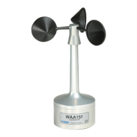
WAA151 User Guide M210293EN-C
14
 Loading...

