Val Controls A/S • Sallingsundvej 5 • DK-6715 Esbjerg N • Tel. +45 7547 0600
vc@valcontrols.com • www.valcontrols.com
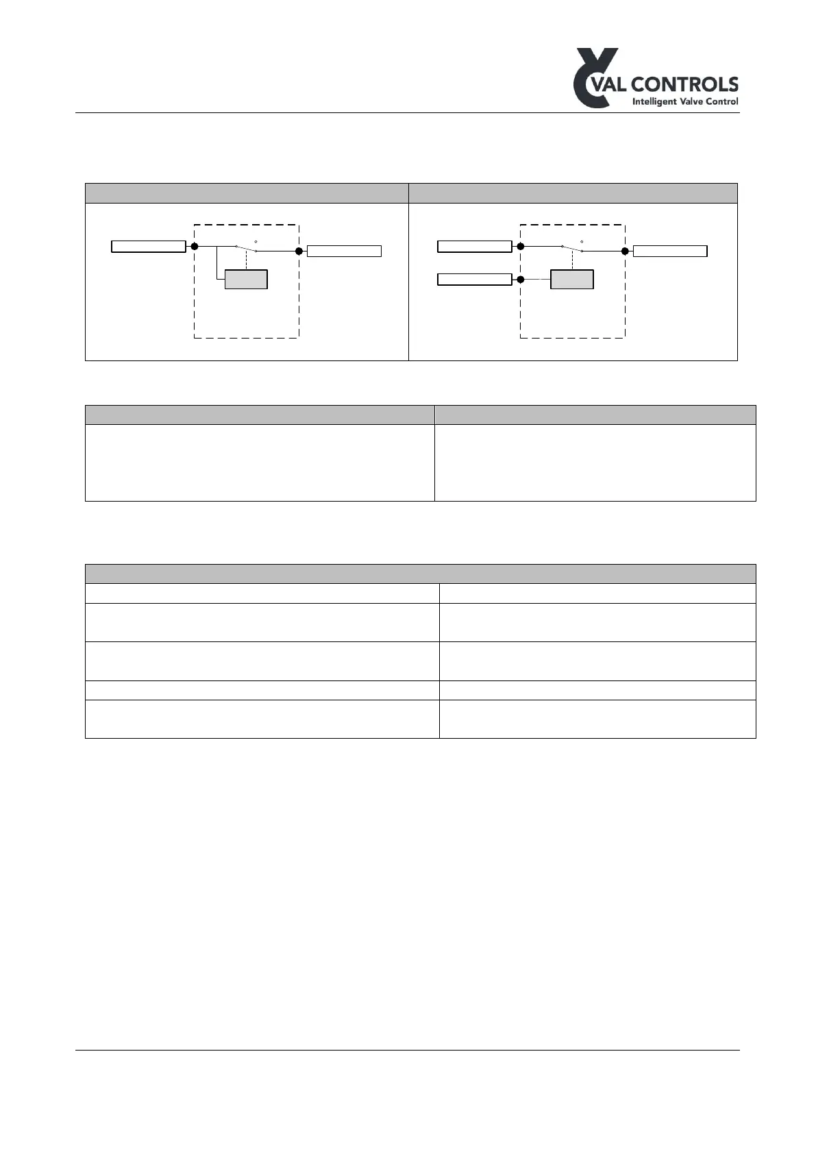
3.6 SIL – PS1, DO11
The units are approved for installation in SIL 1-4 circuits, if installed as described in this manual.
5. PS2 (+)
6. PS2 (-)
21. PS1 (+)
22. PS1 (-)
23. DO11 (+)
24. DO11 (-)
Note: The PS1 and PS2 must be galvanic isolated.
3.6.2 Electrical specifications
Power dissipation, no position sensor/loop or
output lamps are connected.
Power dissipation, with maximum load on all
inputs and outputs
< 5W, the load not included
If PS2 is not used, total load that can be drawn
from all DO/DI/AI ports (except DO11)
 Loading...