512
Thermo E+ 120/200/320 5 Troubleshooting
5.6.4 Resistance check of the temperature
sensor with integrated overheating
protection
Observe the risk of injuries due to increased coolant
temperature.
Prior to removing the temperature sensor, the over-
pressure in the cooling system must be released (e.g.
by opening the cooler lid). Possibly let the heater
before cool down and have collecting container ready
for discharged coolant.
Inspection
• Inspect temperature sensor, plug and cable for
damage and proper fit.
• Remove temperature sensor (see 8.3).
• Perform the electrical test using a measuring device
suitable for resistance measurements.
• The water temperature sensor and the overheating
protection should indicate values according to the
charts (Fig.503 and Fig.504). Preferably the resis-
tance should be measured at an approx. consistent
temperature of 20°C and approx. 100°C (immerse
sensor up to the copper gasket ring into boiling water).
Prior to reading the value, the sensor should be expo-
sed to the temperature for approx. 20 seconds. A
measurement tolerance of +/- 5°C under workshop
conditions is permitted.
• Install temperature sensor (see 8.3).
Resistance vs. temperature charts
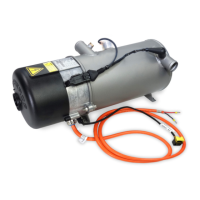
Fig.502
Pin 1 & 3
Pin 2 & 3
Overheat protection
Water
temperature sensor
(PT2000)
(PT500)
Fig.503
Fig.504
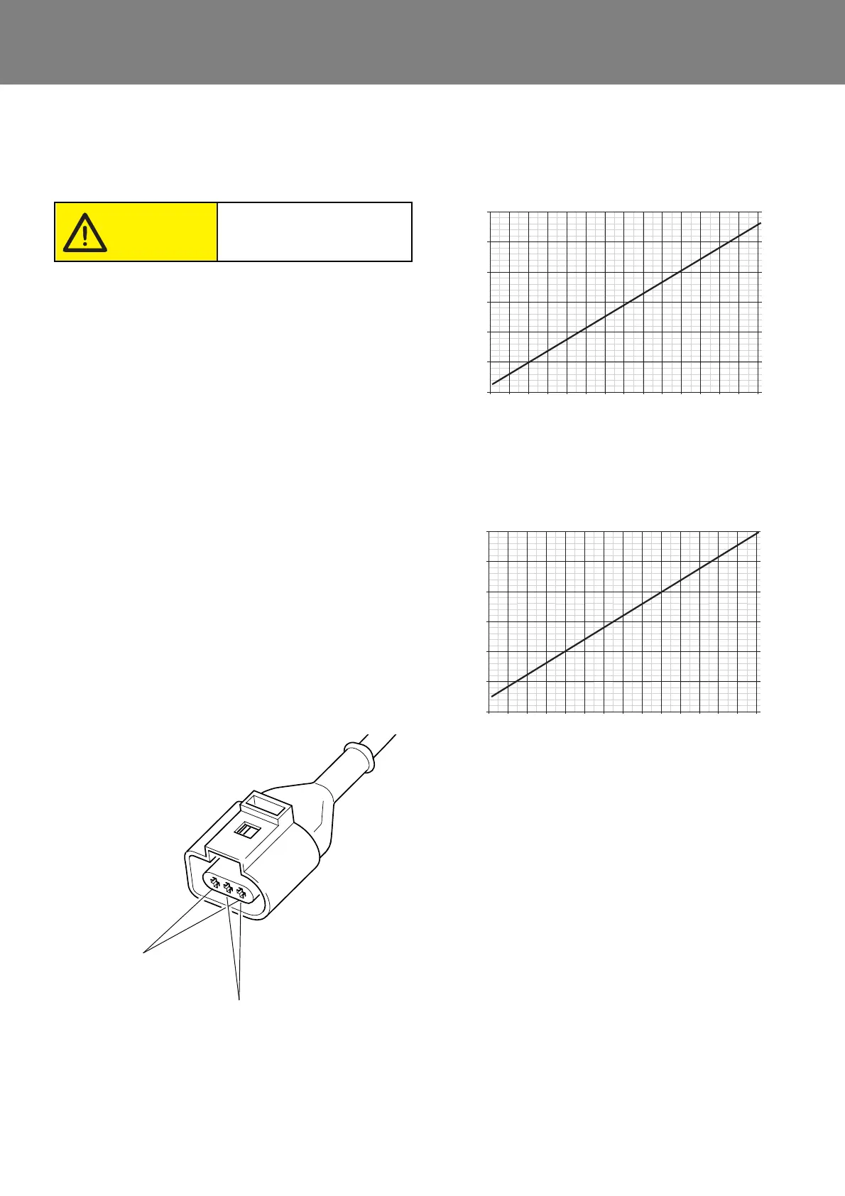
Water temperature sensor (Pin 1 and 3)
Resistance in Ohm
Temperature in °C
-40 -30 -20 -10 0 10 20 30 40 50 60 70 80 90 100
2850
2650
2450
2250
2050
1850
1650
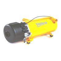
Overheating protection (Pin 2 and 3)
Resistance in Ohm
Temperature in °C
-40 -30 -20 -10 0 10 20 30 40 50 60 70 80 90 100
700
650
600
550
500
450
400