516
Thermo E+ 120/200/320 5 Troubleshooting
5.6.9 Fuel pump inspection
For fuel pump description, see 3.1.3.
NOTE:
The replacement interval of the fuel pump depends on the
fuel used and must be observed, see Maintenance
Schedule Thermo E +.
ATTENTION:
The pump pressure of the fuel pump is adjusted to a
defined value in the factory.
It is permitted to readjust the pump pressure.
The disassembly of the fuel pump is not permitted.
The fuel pump pressure can be checked while the burner
head is removed, using the Component Test menu of DTT
diagnosis.
NOTE:
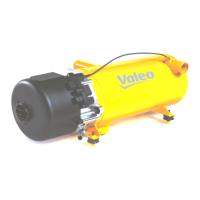
A pressure test gauge with a display range from 0 to 15
bar as well as a bleeding feature is required (Fig.508).
The pump pressure can be checked as follows:
Check without DTT diagnosis
• Remove burner (see 8.2).
• Clamp the burner in the workshop (not in the vehicle).
• Unplug motor and solenoid valve connectors from the
control device.
• Ensure fuel supply.
• Remove fuel nozzle (see 8.10).
• Instead of the nozzle screw the pressure test gauge
into the nozzle block (20 Nm ±2).
NOTE:
Excert counter pressure at the key face of the nozzle
block of the fuel pump using a suitable tool.
• Connect to motor and solenoid valve 24V or 12V, pin
assignment, see Fig. 603.
Observe the direction of rotation of the motor (arrow
on the fan wheel)!
• Open the bleed port at the pressure test gauge until
fuel escapes bubble-free, collect it e.g. with a
cloth.Close the bleed port and read the present pres-
sure at the gauge.
• Compare the actual pressure with the target pressure
in Table 504.
If the specified pressure cannot be reached, it can be
readjusted. For that rotate the adjusting screw (see
Fig.507) max. one revolution. If the prescribed pres-
sure despite readjustement not be achieved or occur
leaks, the fuel pump must be replaced.
• Dismantling in reverse order.
ATTENTION:
Plug the temperature sensor screwed into the heat
exchanger into the control device again.
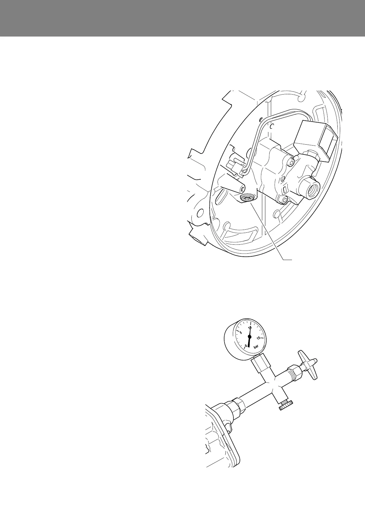
Fig.507 Fuel pump
Fig.508
Adjusting screw
pump pressure
NOTE:
In this figure the fuel pump is shown
removed from heater for clarity.
Pump pressure test gauge
with bleeding feature
(figure exemplary)