BCs160VA
Nov. 15, 1997
SMART-PULP Smart Consistency Transmitter
SMART-PULP HL in digester blow
line installations
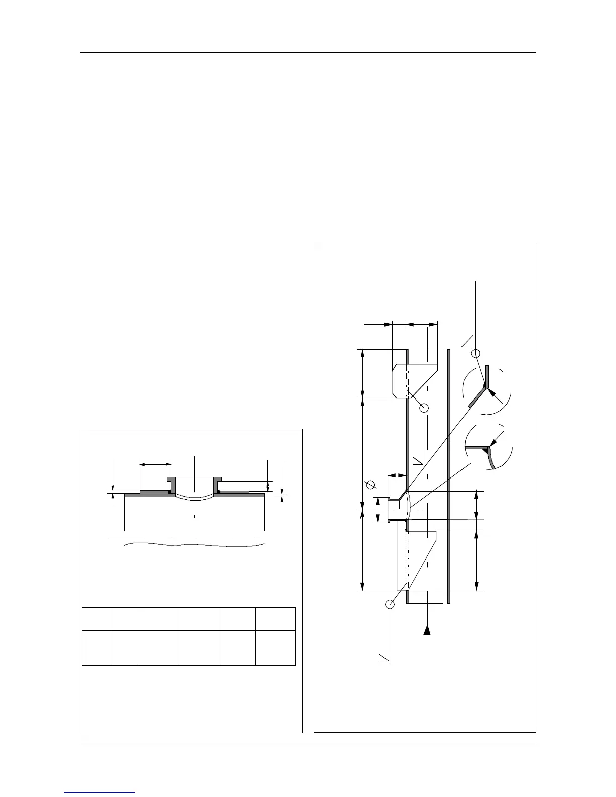
Install the blow line coupling with single bevel weld
at right angles against the pipe, as shown in Figure
1.1.3d. See that the deflector is exactly in line with
the pipe’s center line. The coupling’s lower edge
should be level with the pipe’s inner wall.
Regulations concerning pressurized vessel
installations must be observed when welding the
coupling.
SMART-PULP JL
Installation of the process coupling on fiberglass-
reinforced plastic pipe is illustrated in Figure 1.1.3e.
First make a bevelled hole in the pipe. Then
laminate the process coupling carefully on the pipe
in accordance with lamination instructions.
Figure 1.1.3c Installation for SMART-PULP WS
Figure 1.1.3b Reinforcing the process coupling
7
D = pipes inside diameter
s = pipes wall thickness
Io = width of reinforcing ring
h = thickness of reinforcing ring
NOTE! If the pipes wall thickness is greater than
that given in the table, the thickness of the
reinforcing ring can be correspondingly smaller.
60
95
120
420
*)
54
R
R
90
11 5
85
180
303
**)
FLOW
*) Plate thickness 4 mm
**) Plate thickness 8 mm
Weld
4 Weld
Weld
h
Io
min.
6 mm
s
D
mm
250
400
500
s
mm
4
6
7
p max.
bar
25
25
25
T max.
o
C
100
100
100
Io
mm
32
50
60
h
mm
5
5
6