BCs160VA
Nov. 15, 1997
SMART-PULP Smart Consistency Transmitter
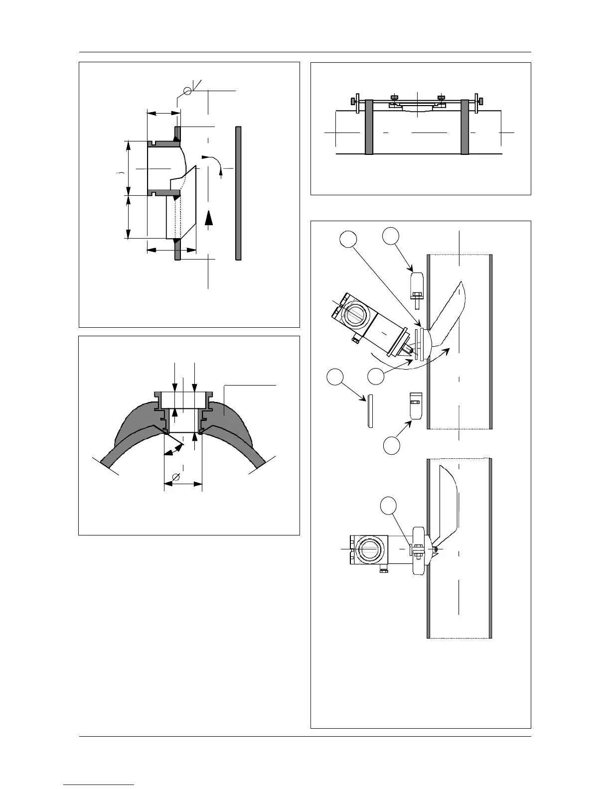
Figure 1.1.3f Process coupling welding guide
Figure 1.1.3g Mounting parts for SMART-PULP
Figure 1.1.3e Installation for SMART-PULP JL
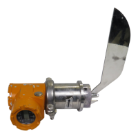
Installing the transmitter
Place PTFE gasket in the groove on the
transmitter’s coupling flange (Fig. 1.1.3g). Attach the
transmitter to the process coupling with mounting
clamp. Before tightening the screws, ensure that the
transmitter’s sensor blade is parallel to the direction
of flow (±1
O
). Use a ruler placed against the bottom
of the aligning slot to align the sensor. Apply 25 N
torque to tighten the screws.
Note! When required, the process coupling can be
shut with a blind flange.
Figure 1.1.3d
Installation of SMART-PULP HL in digester blow line
8
3
1
42
3
welding
3
1
42
3
1. Process coupling
2. Gasket
3. Mounting clamp
4. Plug
5. Aligning slot
5
Ø90
70
80
FLOW
90
O
±0.5
45
O
26
65
50
Lamination
*) Plate thickness 4 mm
*)