1124
Model Code Page
80. Cab and shields
15. 5. 1996
6000--8750 810 6
1. 1. 1995
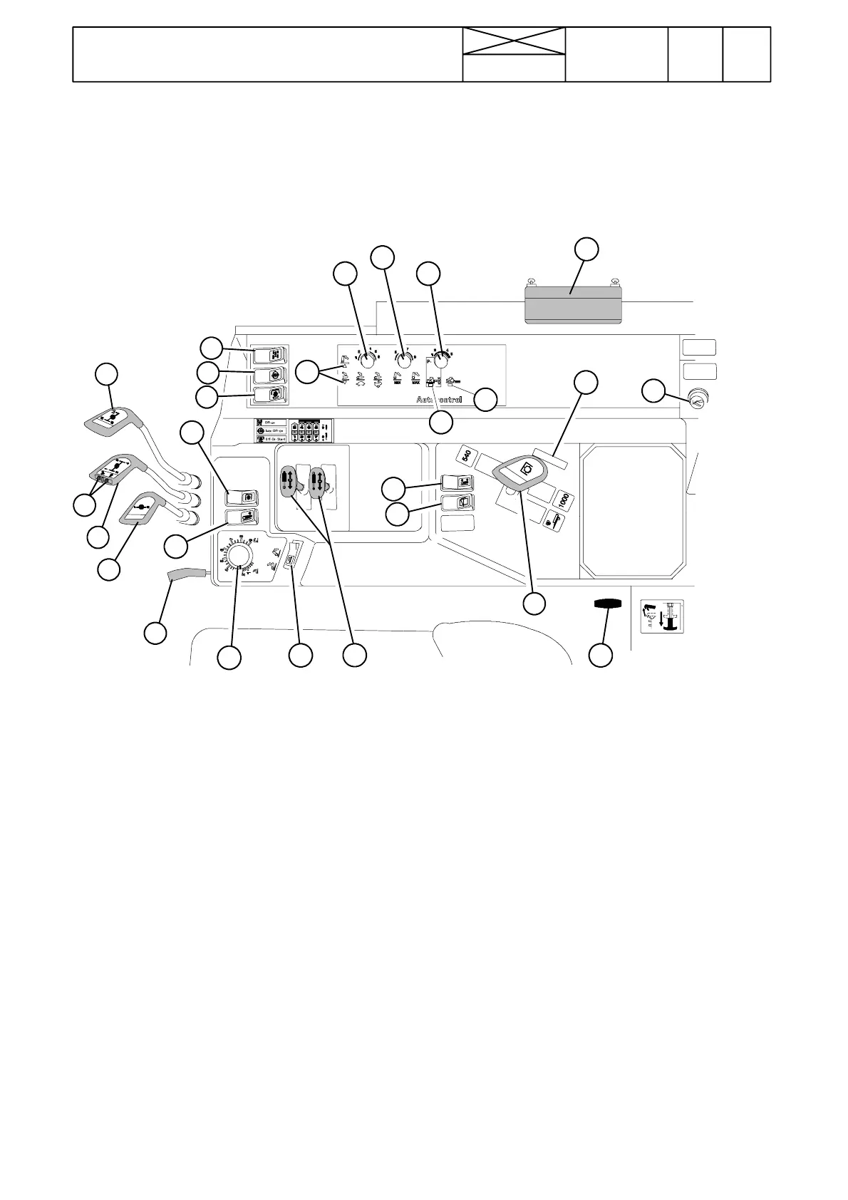
Controls on RH side
A6084---25,3
1
2
3
4
5
6
7
8
9
10
11
1213
14
15
16
17
18
19
20
21 22
23
24
25
26
1. Speed gear lever
2. Push buttons for Delta powershift operation (alternative
equipment)
3. Range gear lever
4. Forward/reverse gear lever
5. Switch for 4WD
6. Switch for differential lock (3 positions)
7. PTO control lever
8. PTO switch (3 positions)
9. Hand throttle lever
10. Position control knob, hydraulic lift
11. Lift/stop/lower switch, hydraulic lift (3 positions)
12. Draft control selector
13. Lowering speed selector
14. Transport height selector
15. Position control indicator light
16. Draft control indicator light
17. Lift/lower indicator light
18. Forced---lowering switch for hydraulic lift, standard on
ACD linkage models, extra equipment on other models.
19. Agrodata---instrument switch (optio n)
20. Lift/lower switch (corresponding push---buttons are lo-
catedonbothmudguards)
21. Auxiliary hydraulic valve levers
22. Pi ck---up hitch rel ease control
23. Side window opening handle
24. Place for remote control (cutter etc.)
25. Rear window wiper + washer (optional equipment)
26.Lighter(alsoforelectricoutput)
Note! Parking brake lever is placed on the LH side of the
driver’sseat. Cab heater controls are fitted on the roof console
(see cabin heater on page 810/8---9).