241
Model Code Page
31. Autocontrol II
1. 1. 1994
6000--8750 311 3
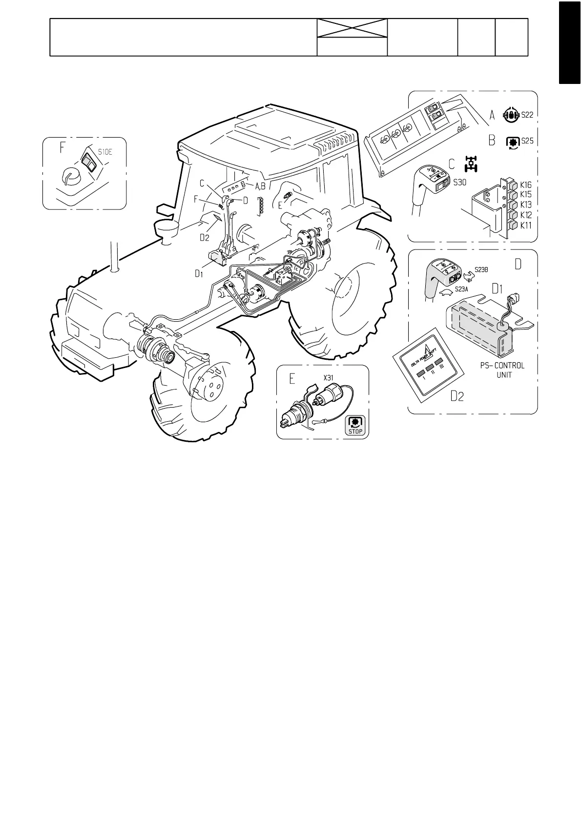
Picture 1. Components of the Autocontrol II
A. Differential lock rocking switch on the right hand side of the seat.
B. PTO rocking switch on the right hand side of the seat.
C. 4WD switch in the range gear lever knob.
D. Delta Powershift push buttons in the speed gear lever knob:
D
1
Delta Powershift control unit
D
2
Delta Powershift indicator lights in the instrument panel
E. PTO emergency stop socket at the rear of the cab
F. Three---position lift/lower switch of the hydraulic power lift
Control relays in the lever console on the driver’s right:
K11: Differential lock relay.
K12: Differential lock relay
K13: Differential lock relay
K15:4WDcontrolrelay.
K16:PTOcontrolrelay.
There is a relay K7 in the fuse box for the four wheel braking.