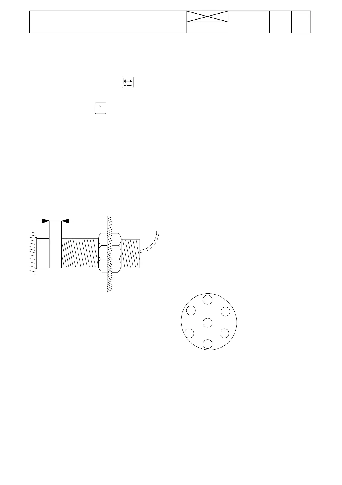
The numbering of
poles can be found
in the plug by the
corresponding pole
Note! Figure
shows the plug
from the lead side.
328
Model Code Page
33. Valmet Agrodata
8. 11. 1990
6000--8400 330 4
B. Checking the sensors and signal from
lift/lower switch
1. Turn on the ignition and:
--- input the working width by pressing the
and followed
by 8888.
--- press the time function key
. Following this the display
should be clear (this indicates that the unit is in order.
--- set switches 5 and 6 for the unit to measure tractor oper-
ations (front side pressed)
2. Now the unit will display the following letters:
--- ” h” (only flashes), when the wheel sensor is activated
--- ” r” (is lit), when the lift/lower switch is in the lifting position
--- ” F” (is lit), when the flow meter blade wheel is revolving
(rocker switches in the implement position)) or if the RPM sen-
sor is activated.
3. If the letter ”h” does not flash, check that the wheel sensor
and magnets are properly located.
Ma
.5mm
4. The distance between the magnet and sensor is max. 5 mm
(magnet must be fitted so that yellow dot points towards the
sensor)
5. If the sensors and magnets are correctly fitted then:
--- disconnect the monitor (not the leads)
--- switch on the ignition
--- measure the voltage between terminal 1 (---) and the follow-
ing; --- terminal 9 (+), supply voltage (about battery voltage)
--- terminal 4 (+), wheel sensor (voltage 0Vwhen sensor
is activated, otherwise the voltage should be 11 ---13,5 V
6. Wheel sensor resistance (is measured between cable
shoes 3 and 4) must be about 33 ohms when the sensor is
activated, otherwise 1 0 k i l o --- o h m s or greater.
7. Check the earth connection by measuring the voltage be-
tween terminals 8 (---) and 6 (+); this should equal battery volt-
age.
8. Set the lift/lower switch to the lifting position and measure
the voltage between terminals 1 (--- ) and 2 (+); this voltage
should be close to zero.
9. Press the lift/lower switch to the lowering position. Now the
voltage should be 11---13,5 V.
10.The defects may be either in the sensors or in the leads. or
the connectors have poor contacts
11.Thesensorsontheimplementarecheckedinthesame
manner. When this is being done, the rocker switches (5 and
6) must be in implement position (the rear side pressed)
C. Connecting the leads from the imple-
ment sensor to the plug poles
Flow meter leads
B l u e t o p o l e 5 ( --- )
Black to pole 6 (+)
Brown to pole 2 (signal)
Piece counter leads
Brown to pole 5 (---)
Blue to pole 6 (+)
Black to pole 2 (signal)
Wheel sensor leads
Blue to pole 3 (signal)
Brown to pole 1 (---)
Sensor for detecting movement of part of implement
Blue to pole 7 (signal)
Brown to pole 5 (---)
.7
3
4
5
6
1
2
Note! The line from the Agrodata unit to the socket can be
checked as follows:
--- input working depth of 8888 and press the time key
--- shunt between the socket terminals no 5 ( ---) and 2 (signal)
and the display should show ”F” (flow meter, piece counter)
--- shunt between terminals no 1 (---) and 3 (signal). The dis-
play should show letter ”h” (only flashes) (wheel sensor).
--- then shunt between terminals no 5 (---) and 7 (signal). The
display should show letter ”r”.