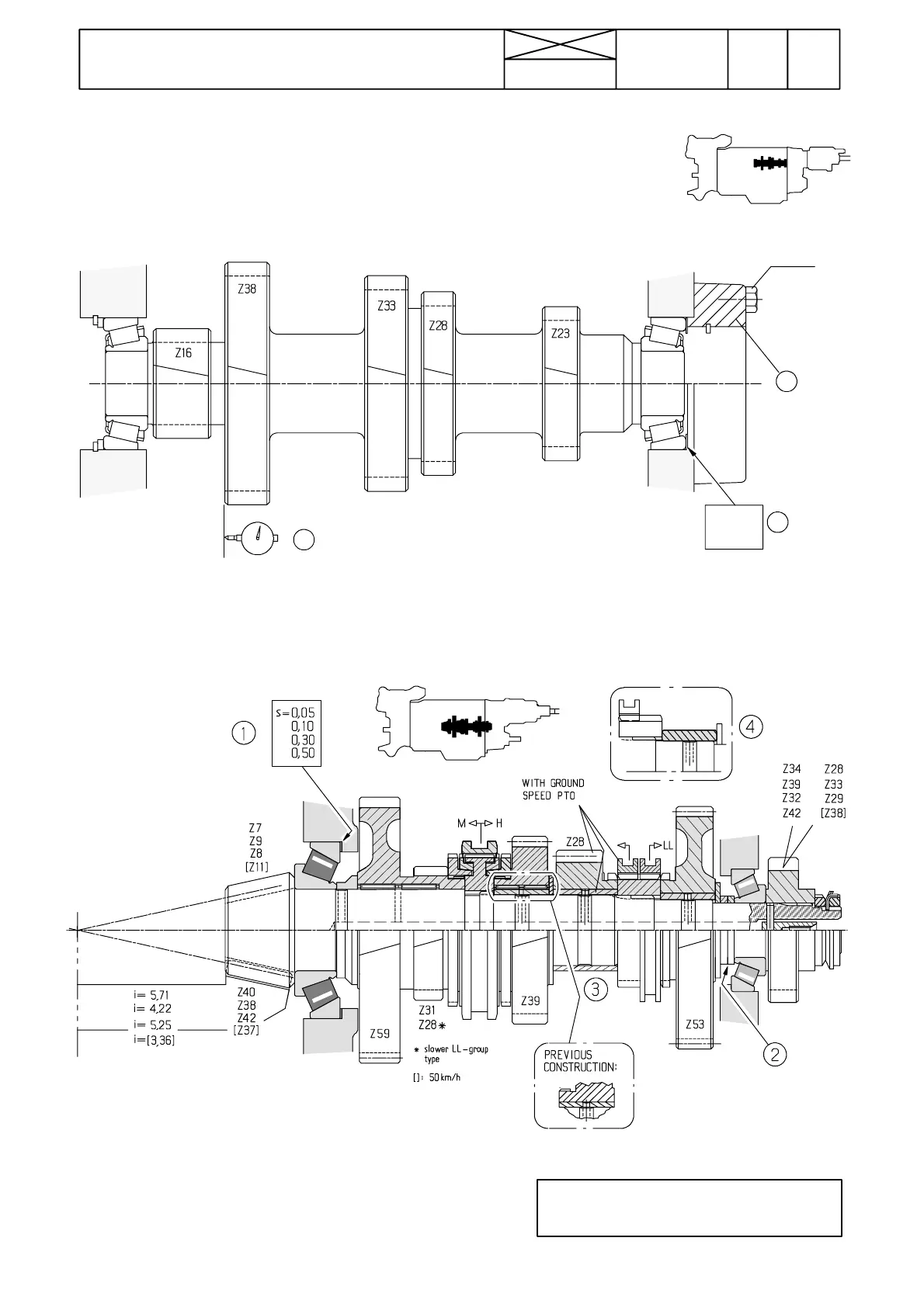
Figure 6. Layshaft (S)
1. Bearing end float is adjusted with shims
2. Note the position of the bearing cover
Layshaft gearwheels Z16 a nd Z38 have been made broader
Figure 7. Bevel pinion shaft (M)
1. Shims for adjusting position of the bevel pinion shaft
2. Bearing preload is adjusted with spacer rings
3. Gear Z28 and AVO coupling only on tractors with ground speed PTO
4. If coupling sleeve LL and gear Z53 removed, there is a sleeve in place.
Note! Figures in brackets = transmission 50 km/h.
Note! On latest shafts there is a needle bearing
fitted inside gear Z39 (for range H). This must
be observed duri ng possibl e repa i r works.
676
Model Code Page
42 Gearbox
15. 5. 1996
8420
6000--8750
15. 4. 1995
0,025...0,075 mm
21---25 Nm
s=0,10
0,15
0,50
1
1
2
AVO