711
Model Code Page
42. Gearbox
1. 8. 1998
6000--8750 423 7
8. 11. 1990
2447
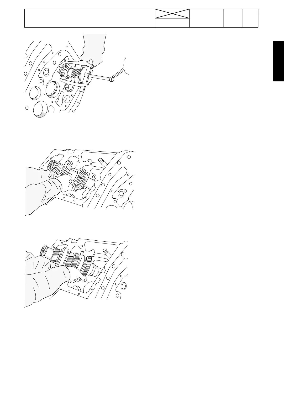
10. Remove the input shaft front end bearing. Support the
shaftsothatitiskepthorizontal.
2448
11. Remove first the layshaft from the housing.
2449
12. Then remove the input shaft.
Important! Before removing the layshaft and the input shaft,
unscrew the lowest screw for the pump drive mechanism
inside the gearbox housing. Also remove the servo valve
block on the LH side of the gearbox, so that the S---shaped
lubricating oil pipe is released.
13. Remove the pump drive mechanism, if needed. Fixing
screws are inside the gearbox housing.
Note! Before detaching the pump drive mechanism, the suc-
tion strainer housing and the suc tion pipes have to be remo-
ved. Also the input shaft lubricating pipe must be removed.
14. Remove bearing outer races from their locations.
3. Checking disassembled gearbox
1. Check the condition of all gear wheels and bearings.
Replace damaged parts with new ones. Lubricate all parts
with oil.
2. Clean the gearbox housing and the lubricating pipes if
necessary. Check the bearing locations.
3. Check the condition of the synchronizing units. The input
shaft synchronizing units can be detached by removing the
rear bear ing with a puller.
Input shaft in transmission 650:
In transmission 650 there is a circlip behind the input shaft
rearmost synchronizer. This circlip must be removed before
removing the input shaft foremostparts(see picture5 onpage
420/7).
Also a spacer has been added between the input shaft gears
Z31 and Z26, with which is adjusted the clearance between
the circlip and thesynchronizer hub to zeroor as small as pos-
sible. The s pacer has marking dots, which indicate the thic k-
ness of the spacer, see picture 5 on page 420/7.
Checking synchronizing ring wear:
--- Place the coupler gear on a flat surface (tapered part
upwards).
--- Place the synchro nizing ring correctly on the tapered part
of the coupler and measure the clearance between the ring
and the gear (i.e. ho w deep the ring is pressed).
Correct clearances:
Input shaft (1---2, 3---4) synchronizing rings (ø 82)
--- new 1,750---1,850 mm (min allowable clearance 0,7 mm)
Pinion shaft synchronizing r ings (M---H) (ø90 mm)
--- new 1,700---2,250 mm (min allowable clearance 1,0 mm).
Assembling synchronizing units
--- place the sliding coupler on a flat surface.
--- put the springs and shoes onto the hub, press them
inwards and place the hub into the sliding coupler so that the
springs and shoes are kept in place.
--- fit three balls (separately) onto the springs and press the
ball inwards and push the parts inside the sliding coupler so
that they are kept in place.
--- when all three balls are in place, push the hub into the sli-
ding coupler.
Note! The bevel pinion shaft and the crown wheel are repla-
ced in pairs bec ause they have been matched together.