1031
Model Code Page
67. Powered front axle Carraro
1. 10. 1999
8450--8950 674 5
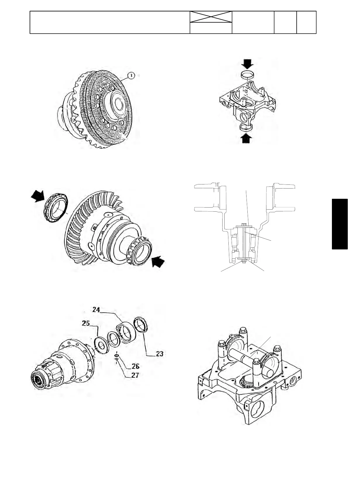
28. Place the crown wheel into place, apply Loctite 270 on
the bolts (1) and tighten them to 70 Nm.
29. Fit the differential bearings onto the housing. When
necessary, warm the bearings up to +80˚C before fitting.
30. Fit the intermediate plate (25), protector (24) and seal
(23) ( if removed). After this the differential can be fastened
onto the support. Observe the o---ring (27) and plate (26).
IMPORTANT! The intermediate plate (25) must be fitted so
thatthebentsideisturnedtothebearingside(seepicture
on page 670/6).
F. Adjusting position of bevel pinion
shaft
31. Fit both bearing outer races into their locations in the
bracket. Cool, when necessary, the bearing races before
fitting.
ET
893 453
ETV 893 452
ET
893 453
ET
893 454
32. Fit the bevel pinion shaft bearings and fasten them with
the special tools (plates ETV 893 453 (2 pcs), ETV 893 454
nut M10 and ETV 893 452 screw M10x100) so that the
bearings rotate freely but without cl earance. Rotate bear-
ings many times.
ETV 893 451
33. Place the measuring rod ETV 893 451 on the differential
bearing bores in the middle of them in the lowest position.
Note! Bearing caps (in picture) can be removed.