1237
Model Code Page
90. Hydraulic system
1. 1. 1995
6000--8750 910 25
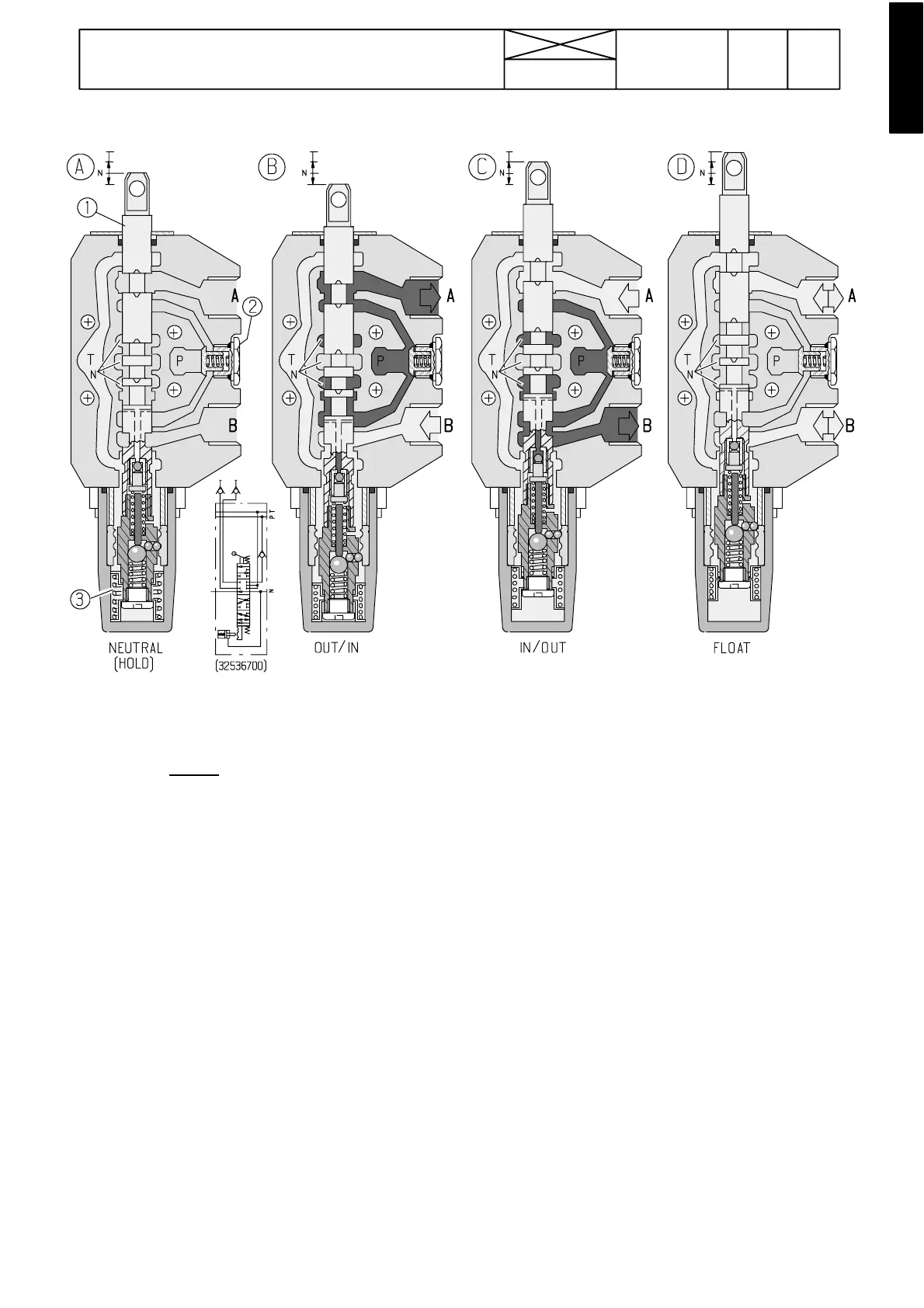
K i c k --- o u t v a l v e
--- Extra equipment (32536700): 2---action, 4 positions (float---
ou t --- ho l d --- i n) k i ck ou t
. Float, out and in---positions can be
locked.
Function:
A: Neutral position: Oil flows from the priority valve (via valve
blocks) through passages N and further to the power lift con-
trol valve. Passages to auxiliary hydraulics (A, B)andthe
non---return valve 2 are closed.
B: Pressure position: When the spool 1 is moved down-
wards, the spool middle part closes the passages N and the
spool upper part opens an oil way to port A. Pressure in pass-
age N increases as in passage P (passages joint together in
the front end plate).
Non---return valve 2 opens and oil flows via port A to the aux-
iliary hydraulics.
Atthesametimethespoolhasopenedareturnpassagefrom
port B to tank passage T. Locking balls lock the spool.
C: When the spool is moved upwards, port B is pressurised
and oil returns via port A.
Pressure return (kick---out) to the neutral position happens
when oil pressure pushes ball+needle at the spool lower end
and releases the locking balls (at a pressure of 14---16 MPa).
The spring spaceis open and allowsoiltobereturnedtopass-
age T. Rest of pressure in the oil space (if greater than 0,2
MPa) can cause returning of the spool to the neutral position.
D: Floating position: Spool 1 has been moved further
upwards. The locking balls lock the spool in position. The
middle passages N open and oil flows through them to the
power lift control valve. Connection between pressure pas-
sage P to ports A and B is closed.
Both ports A and B are connected with tank passage T.
--- When the valve is used as a single---acting valve, an imple-
ment hose should be connected to the upper coupling A.The
return oil flow can be created by moving the spool to the float-
ing position (upwards).
1) Spool
2) Non---return valve
3) Centring springs