290
Model Code Page
32. Electro---hydraulic power lift
6000--8750 320 4
1. 8. 2000
1. 4. 1997
0.2 MPa
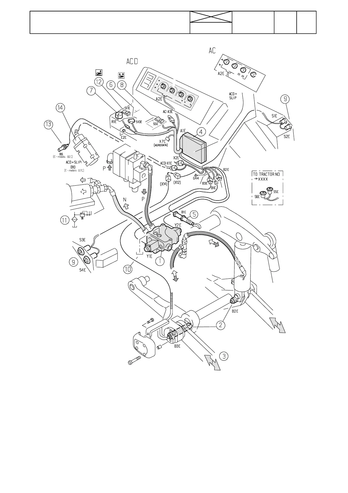
Fig. 2. Electro ---hydraulic power lift AC/ACD
1. Control valve
2. Draft sensors
3. Lower links
4. Electronic unit (different on AC and ACD)
5. Position sensor
6. Lift/stop/lower switch (earlier two positions)
7. Potentiometer for position control
8. Rocker switch (earlier two push buttons)
9. Push buttons, rear mudguards
10. Return oil into the gearbox housing
11. Return oil from control valve
12. Switch, forced lowering (not on earlier models)
13. Gearbox speed sensor, ACD power lift
14. Radar, ACD power lift
Connectors (B1E, B2E and B3E) for position sensor and draft
sensors are placed in the lever console in the cab and they are
accessible after removing the console side panel. On ACD
power lift, the position sensor connector is placed at the end
of the sensor.
Electronic unit (A1E) and the rest of the connectors are also
placed in the lever console on the driver’s right.
Note! ThepictureaboveshowsalsopartsfortheACDpower
lift, see under code 321.