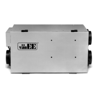
Do you have a question about the vanEE 90 H and is the answer not in the manual?
| Brand | vanEE |
|---|---|
| Model | 90 H |
| Category | Ventilation Hood |
| Language | English |
Diagram illustrating normal air intake and exhaust flow.
Table and diagram showing air flow during defrost cycles and temperature effects.
Diagrams showing the physical measurements of the unit in inches and millimeters.
Installation method for homes with radiant heating, exhausting from humid areas.
Installation method for forced air heating, exhausting from specific points.
Installation method using furnace ducts for fresh and exhaust air flow.
Guidelines for selecting an appropriate location and securely mounting the unit.
Advice on designing duct layout, minimizing bends, and material selection.
Table and examples for determining appropriate duct diameters based on air flow.
Instructions and warnings for installing ductwork and air registers in various areas.
Procedure for connecting insulated and rigid ducts to the unit ports.
Guidelines for placing exterior intake and exhaust hoods, considering distance and height.
Steps for installing drain fittings and creating a trap for condensate drainage.
Wiring diagram for connecting the bronze control panel to the unit.
Wiring diagrams for optional controls like crank timers and push-button switches.
Instructions for safely connecting the unit to the furnace blower control circuit.
Procedure to verify the functionality of the 3-position fan speed switch.
Verification steps for various optional controls like timers and dehumidistats.