Component Identification and
Description of Operation
IT SERIES Industrial True Sine Wave Inverter Owners Manual 16
9-POSITION
TERMINAL BLOCK
+5V
GND
No
connection
connection
INTERNAL
FUNCTION
POWER-ON
LED
ON/OFF
SWITCHES
AUTO
THROTTLE
LOW DC
WARNING
1
2
3
4
5
6
7
8
9
(28) Side entry for negative DC input cable
(29) Side entry for positive DC input cable
(30) Positive DC Input Contact
(31) Negative DC Input Contact
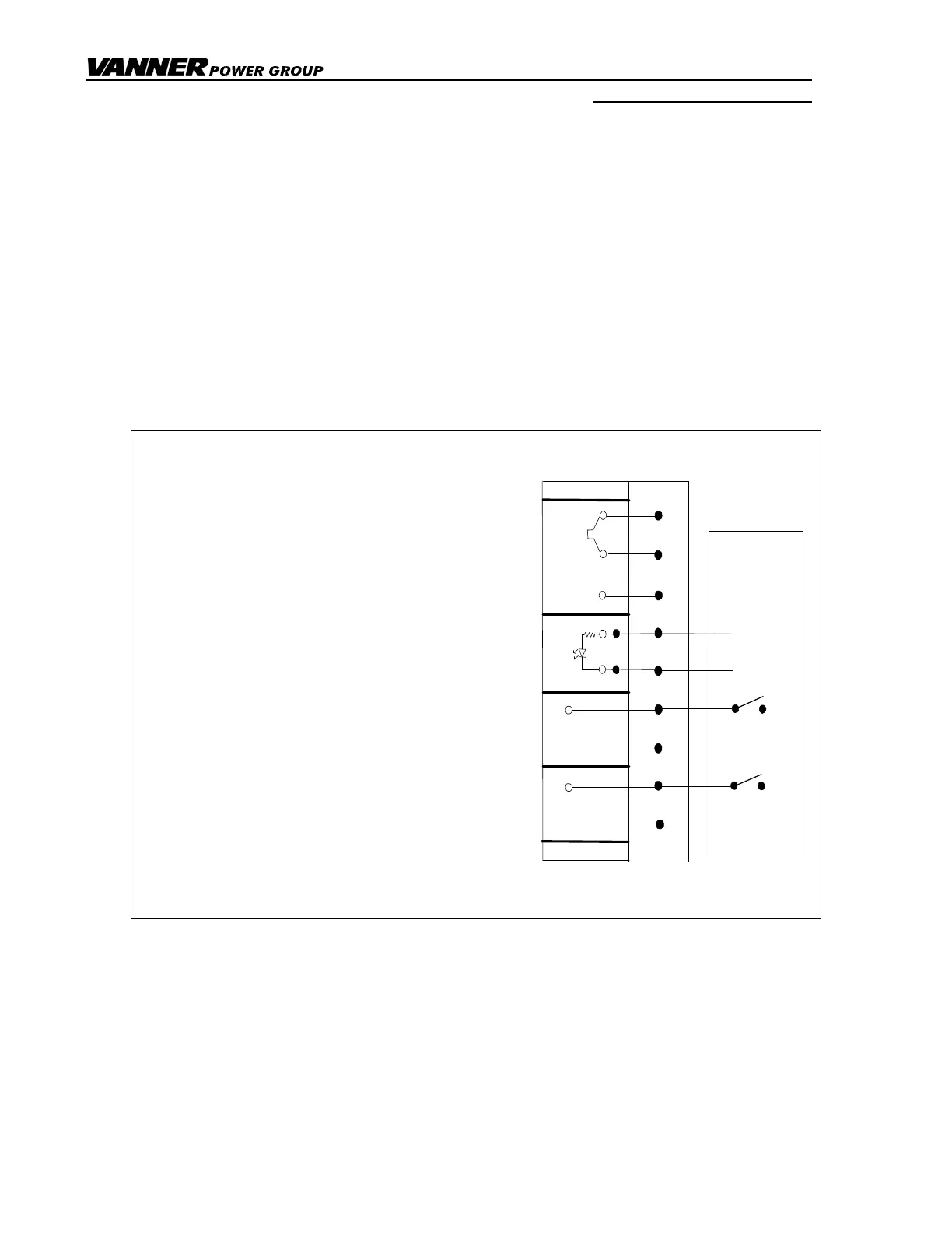
(32) Remote Control Terminal Block
A 9-position terminal block is provided for connecting optional, customer supplied remote control
and remote display wiring. Please note that any wiring to this terminal block is optional.
Figure 6 Remote Control Terminal Block
_____________________________________________
Terminals 1,2 and 3 Remote Switch terminals.
See item (32.1) and Figure 7.
_____________________________________________
Terminals 4 and 5 Remote ‘Inverter ON' LED.
See item (32.2).
____________________________________________
Terminal 6 (Volt Guard Feature) Provides
ground control based on battery
voltage. See item (32.3) & Fig 8.
_____________________________________________
Terminal 8 Provides ground control for a
remote Low Battery Warning
Device. See item (32.5) & Fig 9.
_____________________________________________
Terminal 7 and 9 Terminals 7 and 9 are NOT USED.