Component Identification and
Description of Operation
IT SERIES Industrial True Sine Wave Inverter Owners Manual 17
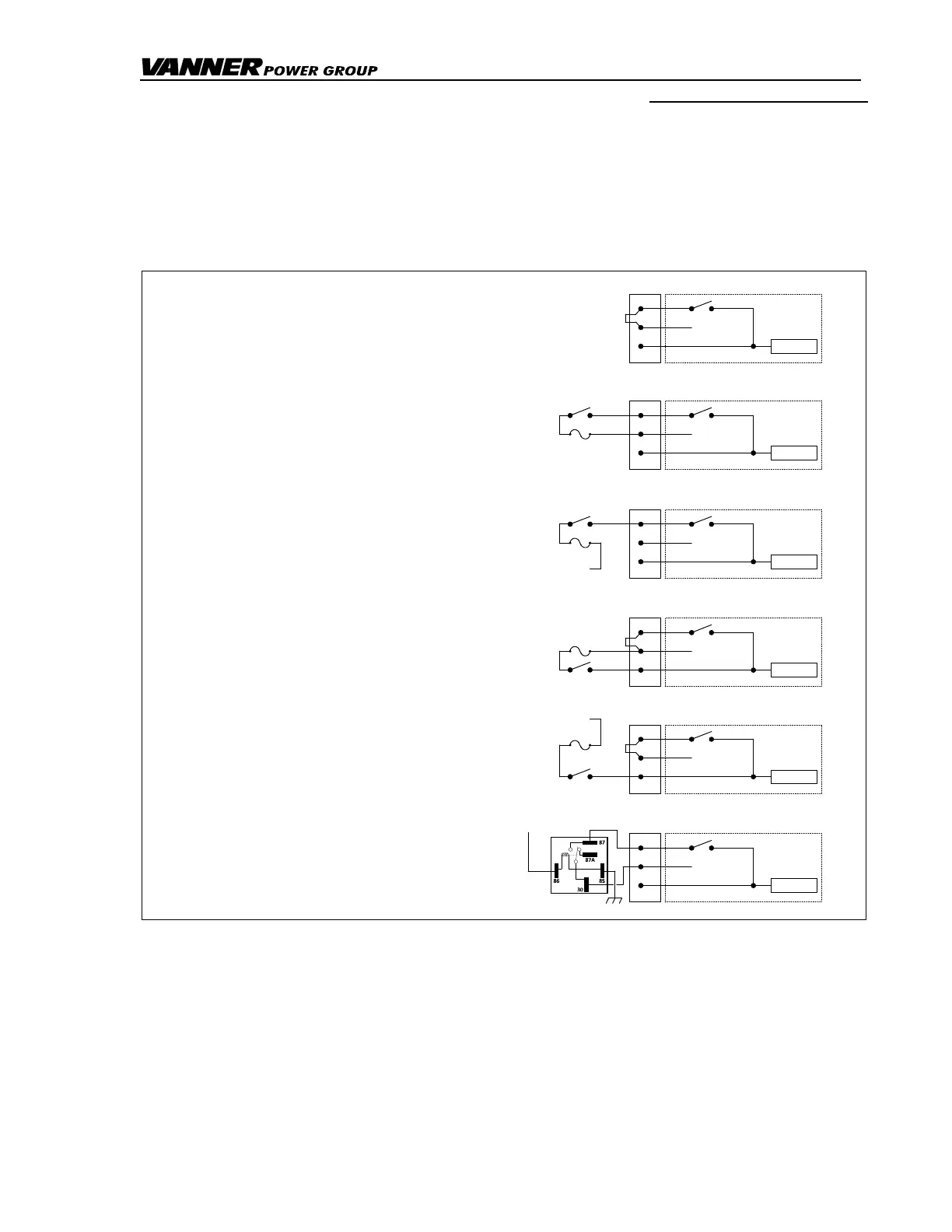
(32.1) Remote ON/OFF Switch Terminals 1, 2 and 3
The IT SERIES Inverter allows five styles of remote control wiring for customers who wish to
supply and install a remote control switch or switches.
Figure 7 Remote Control Switch Wiring variations
1
2
3
Standard
INVERTER ON/OFF
+12/24VDC
9 POS BLOCK
INVERTER
INTERNAL WIRING
JUMPER
No Remote Switch.
(Factory jumper connecting
Terminals 1 and 2.)
1
2
3
Style One
INVERTER ON/OFF
+12/24VDC
9 POS BLOCK
INVERTER
INTERNAL WIRING
SPST
SWITCH
Series Remote Switch
powered by Terminal 2.
(Factory jumper removed.)
1
2
3
Style Two
INVERTER ON/OFF
+12/24VDC
9 POS BLOCK
INVERTER
INTERNAL WIRING
Series Remote Switch
powered externally.
(Factory jumper removed.)
1
2
3
Style Three
INVERTER ON/OFF
+12/24VDC
9 POS BLOCK
INVERTER
INTERNAL WIRING
JUMPER
Parallel Remote Switch
powered by Terminal 2.
(Factory jumper connecting
Terminals 1 and 2.)
1
2
3
Style Four
INVERTER ON/OFF
+12/24VDC
9 POS BLOCK
INVERTER
INTERNAL WIRING
JUMPER
1
2
3
Style Five
INVERTER ON/OFF
+12/24VDC
9 POS BLOCK
INVERTER
INTERNAL WIRING
Standard
automotive relay
Normally open relay
controlled by ignition and
Terminal 2.
(Factory jumper removed.)
2A FUSE
SPST
SWITCH
+12/24VDC
SPST
SWITCH
2A FUSE
SPST
SWITCH
Parallel Remote Switch
powered externally.
(Factory jumper connecting
Terminals 1 and 2.)
+12VDC
2A FUSE
2A FUSE
+12/24VDC
CAUTION: A MAXIMUM 2A FUSE MUST BE USED WHEN INSTALLING STYLE 1 OR 3 REMOTE
ON/OFF SWITCH CONTROL.
(32.2) Remote Inverter Indicator Light (LED) Terminals 4 and 5
(See also item (10) Inverter Indicator Light
Use Terminals 4 and 5 to operate a customer supplied remote Inverter LED through a 470-ohm
resistor. The LED will light when the inverter is ON or in Load Demand Mode. A remote Inverter
LED does not blink when the inverter is in Load Demand Mode.