8
their max current limitation for avoiding the risk of socket damage.
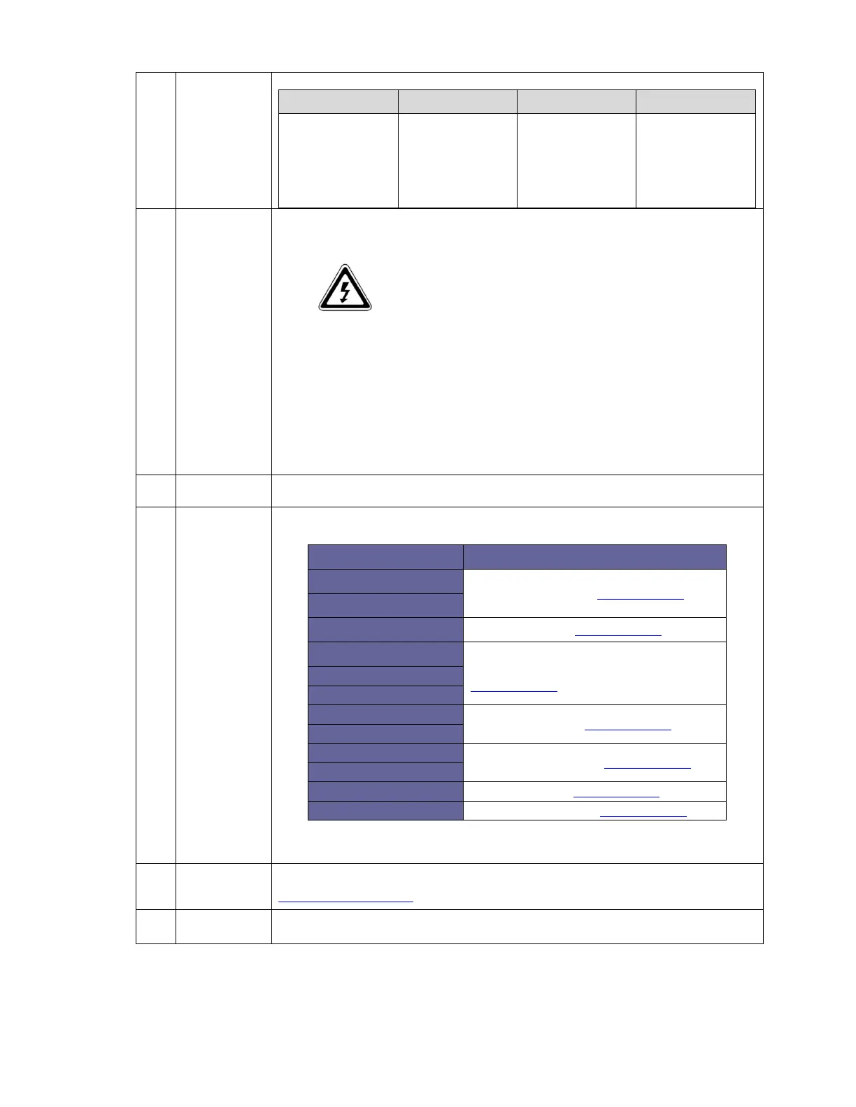
Model No. AC IN AWG AC OUT AWG
GROUNDING AWG
LSC12-2000 30A/10AWG 30A/10AWG 30A/10AWG
C
Chassis
ground
This connection is used to tie the exposed chassis of the inverter to the DC grounding
system. This terminal accepts CU/AL conductors from #14 to #2 AWG (2.1 to 33.6 mm2).
WARNING!
The ground wire offers protection only if the cabinet of the unit is
connected to the safety ground. Connect the chassis ground.
Terminal to the hull or the chassis.
Refer to local regulations on these issues!
For safety purposes the neutral conductor (N) of the AC output must be connected to the
earth (PE / GND) when the unit is in inverter operation. When utility power is available on
the AC input, and the unit is in charger mode, this connection must be disabled again.
In some applications automatic connection between the neutral conductor (N) and earth
(PE / GND) is not required or acceptable. Therefore the automatic connection between the
neutral conductor (N) and earth (PE / GND) is enabled by default.
D
Main switch The switch for 1.Power ON 2.Power Off 3.Remote Mode.
E
DIP switch
Dip Switch Function
S1
Output Voltage Select (refer to 3-2-1-1)
S2
S3 Frequency Select (refer to 3-2-1-2)
S4
AC Input Current Limit Select
(refer to 3-2-1-3)
S5
S6
S7
Battery Type Select (refer to 3-2-1-4)
S8
S9
Charger Current Select (refer to 3-2-1-5)
S10
S11 DC Source on/off (refer to 3-2-1-6)
S12 Saving Function on/off (refer to 3-2-1-7)
F
Function LED
From left to right is “Battery voltage”’, ”AC output load”, “Charger stage”, “System status”
*For details, refer to 3-2-2
G
AC input
breaker