11
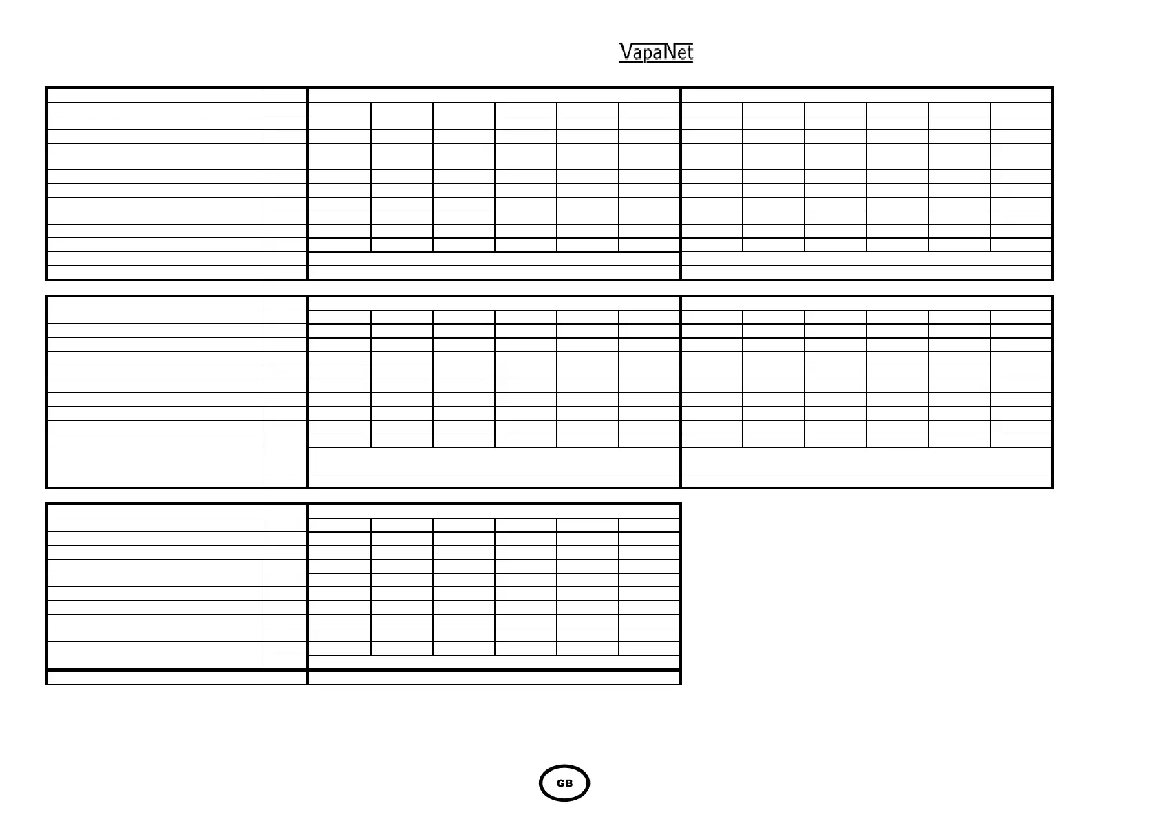
1.5 Cylinder Electrical demand loads
Model Ref.
LEC05 LE09
Nominal Output Kg/hr 5 5 5 5 5 5 9 9 9 9 9 9
Voltage V 200 230 380 400 415 440 200 230 380 400 415 440
Power input rating per cylinder Kw 3.73 3.71 3.78 3.81 3.78 3.83 6.71 6.76 6.77 6.79 6.7 6.74
Electrical Supply Ph's Ph+N or
2Ph
Ph+N or
2Ph
Ph+N or
2Ph
Ph+N or
2Ph
Ph+N or
2Ph
Ph+N or
2Ph
Ph+N or
2Ph
Ph+N or
2Ph
Ph+N or
2Ph
Ph+N or
2Ph
Ph+N or
2Ph
Ph+N or
2Ph
No. of electrodes 2 2 2 2 2 2 2 2 2 2 2 2
Full load Current per cylinder A 22.5 19.5 12 11.5 11 10.5 40.5 35.5 21.5 20.5 19.5 18.5
Maximum overcurrent per cylinder A 33.75 29.25 18 17.25 16.5 15.75 60.75 53.25 32.25 30.75 29.25 27.75
Number of cylinders & supply 2 2 2 2 2 2 2 2 2 2 2 2
2 Supplies @ Fuse Rating/phase A 32 32 16 16 16 16 63 50 32 32 32 25
Supply cable terminals mm
2
4 4 4 4 4 4 10 10 10 10 10 10
Wiring diagram A4-LZD-559 cyl 1 and A4-LZD-595 cyl 2 A4-LZD-559 cyl 1 and A4-LZD-595 cyl 2
Cabinet size 4 4
Model Ref.
LEC18 LEC30
Nominal Output Kg/hr 18 18 18 18 18 18 30 30 30 30 30 30
Voltage V 200 230 380 400 415 440 200 230 380 400 415 440
Power input rating Kw 13.34 13.36 13.35 13.48 13.39 13.57 22.38 22.43 22.35 22.38 22.32 22.41
Electrical Supply Ph's 3Ph 3Ph 3Ph 3Ph 3Ph 3Ph 3Ph 3Ph 3Ph 3Ph 3Ph 3Ph
No. of electrodes 3 3 3 3 3 3 6 6 3 3 3 3
Full load Current per cylinder A 46.5 40.5 24.5 23.5 22.5 21.5 78 68 41 39 37.5 35.5
Maximum overcurrent per cylinder A 53.475 46.575 28.175 27.025 25.875 24.725 89.7 78.2 47.15 44.85 43.125 40.825
Number of cylinders & supply 2 2 2 2 2 2 2 2 2 2 2 2
2 Supplies @ Fuse Rating/phase A 50 50 32 32 32 32 100 80 50 50 50 50
Supply cable terminals mm
2
10 10 10 10 10 10 35 35 35 35 35 35
Wiring diagram A4-LZD-559 cyl 1 and A4-LZD-595 cyl 2 A4-LZD-561 & A4-
LZD-596
A4-LZD-559 cyl 1 and A4-LZD-595 cyl 2
Cabinet size 4 4
Model Ref.
LEC45
Nominal Output Kg/hr 45 45 45 45 45 45
Voltage V 200 230 380 400 415 440
Power input rating Kw 33.57 33.65 33.79 33.85 33.93 33.45
Electrical Supply Ph's 3Ph 3Ph 3Ph 3Ph 3Ph 3Ph
No. of electrodes 6 6 6 6 6 6
Full load Current per cylinder A 117 102 62 59 57 53
Maximum overcurrent per cylinder A 134.55 117.3 71.3 67.85 65.55 60.95
Number of cylinders & supply 2 2 2 2 2 2
2 Supplies @ Fuse Rating/phase A 160 125 80 80 80 80
Supply cable terminals mm
2
35 35 35 35 35 35
Wiring diagram A4-LZD-561 cyl 1 and A4-LZD-596 cly 2
Cabinet size 4
The LEC units have two cylinders the table
refers to the maximum operating current of
each cylinder.
Each LEC unit requires two power suppliers, one
to each of the cylinder at the table rating above.
Both supplies should be routed through a six pole
switch fuse isolator within 1 meter of unit .