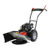
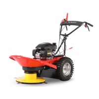
Lucina MaX
2.6 Manufacturer address
VARI, a.s. Phone: (+420) 325 607 111
http://www.vari.cz http://katalognd.vari.cz
Opolanská 350 Fax: (+420) 325 607 264
Libice nad Cidlinou (+420) 325 637 550
289 07 Czech republic E-mail: vari@vari.cz
Web: http://www.vari.cz
2.7 Picture appendix
The picture appendix is common for all the language versions. You can find it at the end of this manual in the Chapter 5 EN Pictures
on the page 54.
1 Place for holding at the back (frame U-tube)
2 Screen holder
3 Dismounted disc cover
4 Place for holding the machine at the front(cutting disc)
5 Tilted handlebars in the package (transport position)
6 Bag
7 Side and rear screens
8 Handlebars fastening bolt
Pict. 1: Unwrapping the machine
1 Disc drive clutch level
2 Wheel drive clutch lever
3 Handlebars fastening bolt
4 Accelerator lever (gas lever)
5 Side screen fastening bolt
6 Side screen
7 Cutting disc
8 Blades (4 pieces)
9 Cover between wheels
10 V-belt cover
11 Frame - tube
12 Handle
13 Engine
14 Fuel tank lid
15 Wheel
16 Gearbox cover
17 Fabric eyelet
Pict.2: Description of the main parts
Position STOP:
Engine is not running (position 1 )
➢ Used for turning off the running engine.
➢ Putting the machine out of service.
➢ Refuelling
➢ Machine transport
Position MIN:
Engine is running at idle. (position 2 turtle)
➢ Short work break
Position MAX:
Engine is running at maximum rpm. (position 3 hare)
➢ Working position
Position CHOKE:
Engine is running. (position 4 )
➢ Cold engine start
Pict. 4: Positions of accelerator lever
Pict. 5: Cutting width Pict. 11: Adjustment of the wheel drive tightening pulleys
Pict. 6: Lubricating point Pict. 12: Disc drive clutch lever – brake
Pict. 7: Lubricating point Pict. 13: V-belt track
Pict. 8: Lubricating point Pict. 14: Safety pictogram - Machine wheel drive
Pict. 9: Lubricating point Pict. 15: Safety pictogram - Starting up the disc
Pict. 16: Safety pictogram – Combined sticker Location on the machine
Pict. 17: Safety pictogram - Arrow direction of turning Location on the machine
Pict. 18: Safety pictogram - Restricted area
Location on the machine
Location on the machine
Pict. 19: Safety pictogram - Guaranteed sound power level
Pict. 20: Upper position
Pict. 21: Fixation of lever
Pict. 22: Working position
Pict. 23: Speed higher
Pict. 24: Speed lower
26
Revize 05/2014