c
e
r
t
i
f
i
e
d
Q
M
-
S
y
s
t
e
m
g
e
p
r
ü
f
t
e
s
Q
M
-
S
y
s
t
e
m
ISO 9001
EN 29001
Installation, Operating, and Maintenance Instructions
Series 64.1
VAT Vakuumventile AG, CH-9469 Haag, Schweiz
Tel ++41 81 771 61 61 Fax ++41 81 771 48 30 Email reception@vat.ch http://www.vatvalve.com
225590EE
2005-04-26
16/16
9.4 User Information and Recommendations
9.4.1 Operation sequence of PM controller
Initialization
Prior to pressure control the setup sequence needs to be performed. Please refer to chapter ‚2.3 PM Configuration (setup sequence)‘
Pressure Control Sequence in LOCAL mode or with ‘S:’ Command
Pressure control starts after «PRESSURE MODE» and a «SET POINT» is selected or after a pressure control command is sent to the PM
controller.
9.4.2 How to optimize sensor signal resolution
Full scale signal of the sensor is converted by a 12bit AD converter. The resolution depends therefore on the Voltage Range.
Example: Sensor: 1 Torr full scale, 0 to 10 VDC output;
Required pressure range: 0 to 120 mT
Standard sensor setup on PM: Voltage Range: 0-10V, Display Range: 1, Display Unit: Torr
→ Resolution of PM controller: 1Torr * 0.03% = 0.3mT
Recommended for sensor setup: Voltage Range: 0-2V, Display Range: 0-200, Display Unit: mTorr
→ Resolution of PM controller: 200mTorr * 0.03% = 0.06mT
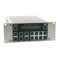
Valve
Position
Control Mode
Pressure
Valve
OPEN
Gas flow