c
e
r
t
i
f
i
e
d
Q
M
-
S
y
s
t
e
m
g
e
p
r
ü
f
t
e
s
Q
M
-
S
y
s
t
e
m
ISO 9001
EN 29001
Installation, Operating, and Maintenance Instructions
Series 64.1
VAT Vakuumventile AG, CH-9469 Haag, Schweiz
Tel ++41 81 771 61 61 Fax ++41 81 771 48 30 Email reception@vat.ch http://www.vatvalve.com
225590EE
2005-04-26
9/16
9 Engineering Information
9.1 Wiring of Connectors
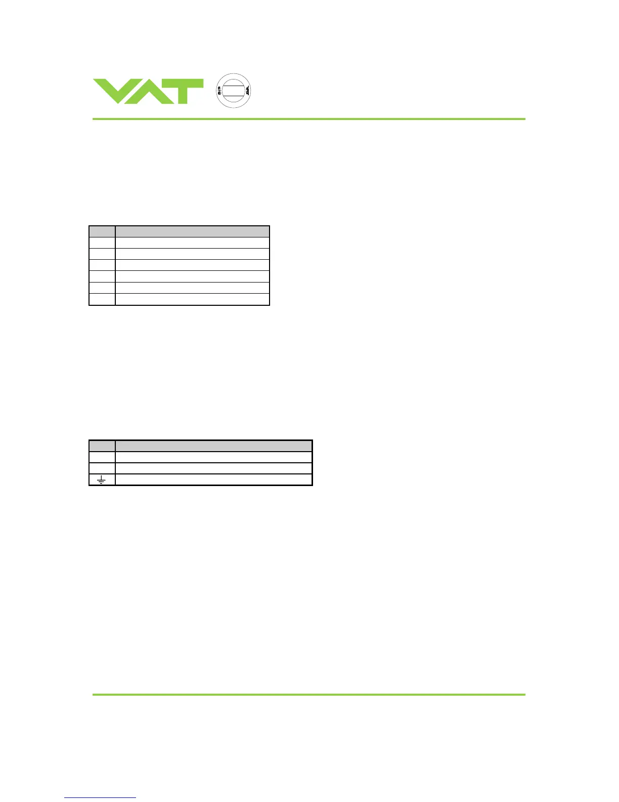
9.1.1 Connector for sensor 1 and sensor 2
PIN Description
1 Connect shield of sensor cable
7 (-) Sensor signal
8 (+) Sensor signal
10
+ 15 VDC, max., ±5%, 1400 mA max. *
12 0 VDC
14
- 15 VDC, max., ±5%, 1400 mA max. *
*) total current for both sensors is 1400mA
Mind: Do not connect other Pins than indicated in the table above!
Recommendations:
- Use only shielded sensor cables
- Keep cable as short as possible, but locate it away from noise sources
- Use power supply of the PM controller for the sensor
- Mount the sensor, especially capacitance diaphragm gauges, at a place free of mechanical shock and/or vibrations
- Observe recommendations of sensor manufacturer
9.1.2 Connector for mains
PIN Description
L Phase (100 - 240 VAC +/-10%, 50/60Hz, 150 VA max.)
N Neutral
Ground