c
e
r
t
i
f
i
e
d
Q
M
-
S
y
s
t
e
m
g
e
p
r
ü
f
t
e
s
Q
M
-
S
y
s
t
e
m
ISO 9001
EN 29001
Installation, Operating, and Maintenance Instructions
Series 64.1
VAT Vakuumventile AG, CH-9469 Haag, Schweiz
Tel ++41 81 771 61 61 Fax ++41 81 771 48 30 Email reception@vat.ch http://www.vatvalve.com
225590EE
2005-04-26
3/16
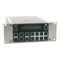
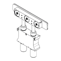
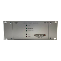
Confirm that hardware is complete (picture 1)
(1) Adaptive Pressure Controller PM-4 or PM-5, hereafter referred to as PM controller.
For PM controller with power failure option confirm that battery life has not expired (see chapter ‚4 Preventive Maintenance‘)
(2) Connection cable valve - PM controller: VAT part number 640CV-99L .
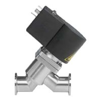
(3) VAT Series 64 control valve
(4) Mains connection, wiring information see chapter ‚9.1.2 Connector for mains‘
(5) Interface cable, wiring information see chapter ‚9.1.3 Connector for interface‘
(6) Sensor 1 (standard) and 2 (option)
(7) Cable for sensor 1 and 2, wiring information see chapter ‚9.1.1 Connector for sensor 1 and sensor 2‘
Install hardware
PM controller must be switched off during installation.
- Install VAT control valve (3) according to the Installation, Operating and Maintenance Instruction Manual of the VAT Series 64 control
valve.
- Install sensor(s) (6) according to the recommendations of the sensor manufacturer
- Install PM controller (1) into control rack.
- Connect valve cable (2) to control valve and then to PM controller (connector: valve)
- Connect sensor cable (7) to sensor(s) and then to PM controller (connector: sensor 1 / sensor 2)
- For remote operation, connect interface cable (5) to PM controller (connector: interface)
- Connect mains cable (4) to PM controller