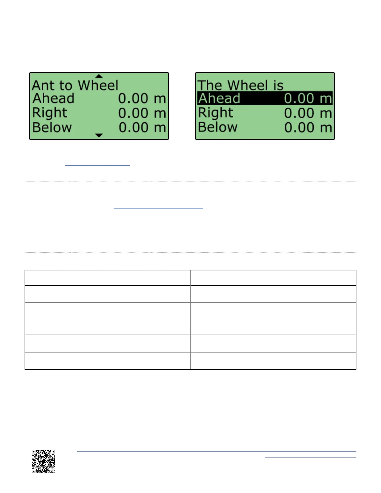
8. Scroll to the 'Ant to Wheel' menu and enter the distances measured between the wheel speed reference point and
the antenna. The reference point is the centre point between the rear wheels, as shown in the image above.
9. Before testing commences, ensure that the wheel speed CAN inputs have been configured
through VBOX Setup Software.
Initialisation
When using IMU integration, an initialisation phase is required when the IMU is first connected to the VBOX after
being set up. This will be run through automatically after the VBOX has successfully gained satellite lock. When the IMU
LED on VB3i front panel has turned a flashing green, the initialisation is complete.
Note: If you are using a VB3i-V1, which has no IMU LED, read the LED indicators section below for LED behaviour.
LED Indicators VBOX 3i (V2/V3/V4/V5) and IMU04
VBOX 3i LED Colour Description
Solid Orange IMU enabled, no IMU connected.
Flashing Orange
SAT lock OK. 30 second stationary initialisation in
progress. If vehicle moves, LED will continue to flash
until 30 seconds stationary completed.
Flashing Green Initialisation complete – movement not yet detected.
Solid Green Movement detected – IMU integration working OK.
https://en.racelogic.support//Product_Info/VBOX_Data_Loggers/VBOX_3i_Range/VBOX_3i_User_Guide_(All_Variants)/12-2_-
_VB3i_IMU_Integration_-_Roof_Mounted
89