SummarySummary
MIG SERIES EQUIPMENT MIG SERIES EQUIPMENT
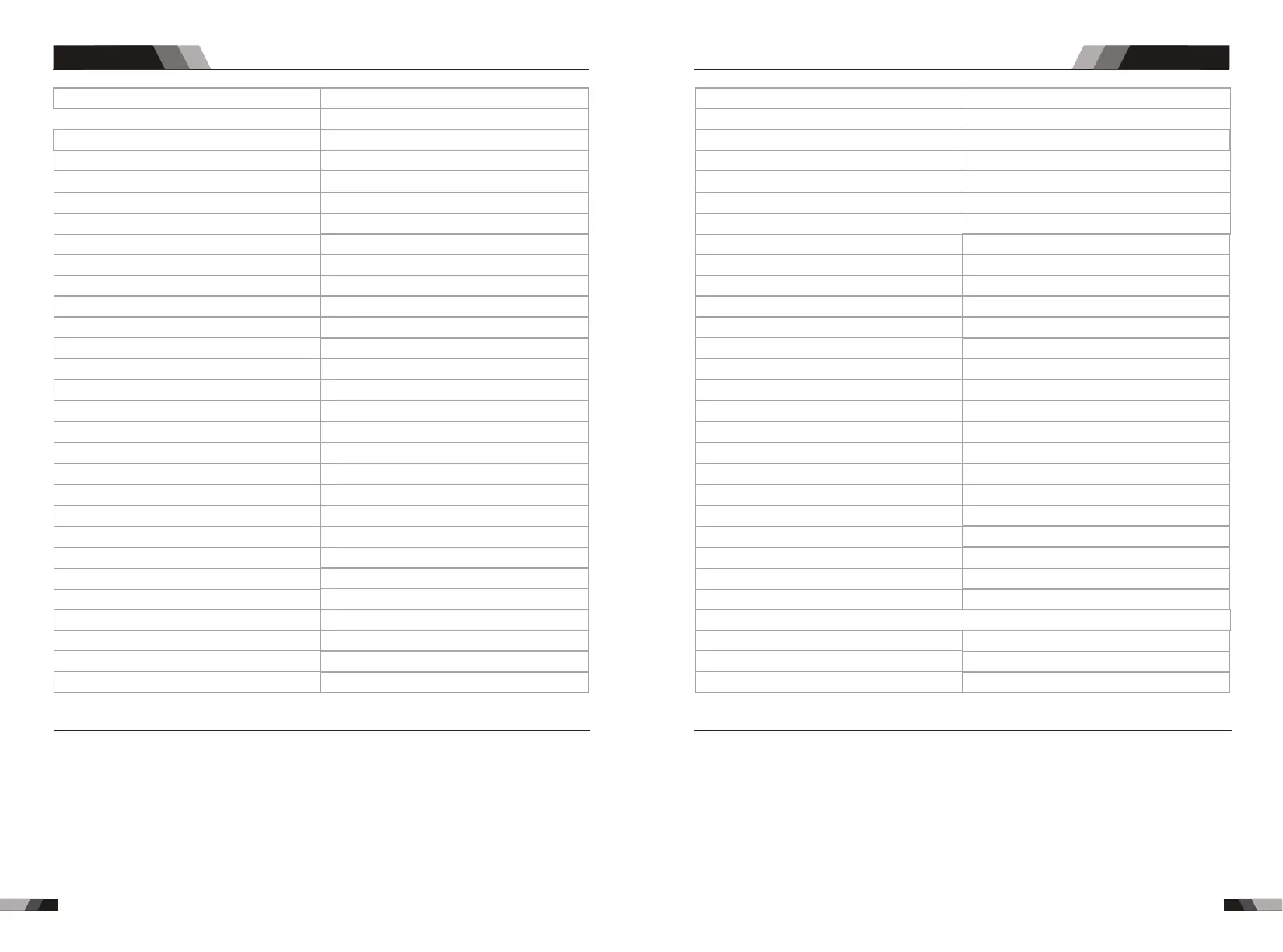
8kg
30-185 A
30-160 A
10-180 A
18.9 A
30A
10KVA
H391mmxB153mmxT282mm
185A@ 40%23V 114A@ 100%20V
160A@ 40%26V 101A@ 100%24V
180A@ 40%17.2V 114A@ 100%14.6V
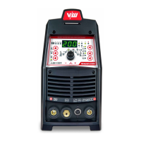
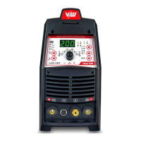
VECTOR DIGITALF MIG185
IP23
F
3s
EN 60974-1 / IEC 60974-1
1
230V +/- 15%
50/60Hz
10-25 V
2.5-15
5kg
0.6/0.8/1.0
80%
0.8
60V DC
Weight
Dimensions
Cooling
Welder Type
European Standards
Number of Phases
Nominal Supply Voltage
Nominal Supply Frequency
Welding Current Range (MIG Mode)
Welding Current Range (MMA Mode)
Welding Current Range (TIG Mode)
Single Phase Generator Requirement
Duty cycle, 40°C, 10 min(MIG)
Duty cycle, 40°C, 10 min(MMA)
Duty cycle, 40°C, 10 min(TIG)
Open Circuit Voltage
Protection Class
Maximum Input Current
Effective Input Current
Wirefeeder Speed Range
Wire roll weight
Wire roll diameter
Thickness of material
Efficiency
Power Factor
Output Voltage Range
Insulation Class
Gas Follow
Description
Note 1: The Effective Input Current should be used for the determination of cable size & supply
requirements.
Note 1: The Effective Input Current should be used for the determination of cable size & supply
requirements.
Note 2: Generator Requirements at the Maximum Output Duty Cycle. Note 2: Generator Requirements at the Maximum Output Duty Cycle.
NOTE NOTE
Note 3: Motor start fuses or thermal circuit breakers are recommended for this application. Check local
requirements for your situation in this regard.
Note 3: Motor start fuses or thermal circuit breakers are recommended for this application. Check local
requirements for your situation in this regard.
Due to variations that can occur in manufactured products, claimed performance, voltages, ratings, all
capacities, measurements, dimensions and weights quoted are approximate only. Achievable capacities
and ratings in use and operation will depend upon correct installation, use, applications, maintenance
and service.
8kg
30-225 A
30-170 A
10-200 A
24.8 A
41.9A
15KVA
225A@ 35%25V 133A@ 100%21V
170A@ 35%26.8V 100A@ 100%24V
200A@ 35%18V 118A@ 100%14.7V
VECTOR DIGITALF MIG225
IP23
F
3s
EN 60974-1 / IEC 60974-1
1
230V +/- 15%
50/60Hz
10-25 V
2.5-15
5kg
0.6/0.8/1.0
80%
0.8
60V DC
H391mmxB153mmxT282mm
Weight
Dimensions
Cooling
Welder Type
European Standards
Number of Phases
Nominal Supply Voltage
Nominal Supply Frequency
Welding Current Range (MIG Mode)
Welding Current Range (MMA Mode)
Welding Current Range (TIG Mode)
Single Phase Generator Requirement
Duty cycle, 40°C, 10 min(MIG)
Duty cycle, 40°C, 10 min(MMA)
Duty cycle, 40°C, 10 min(TIG)
Open Circuit Voltage
Protection Class
Maximum Input Current
Effective Input Current
Wirefeeder Speed Range
Wire roll weight
Wire roll diameter
Thickness of material
Efficiency
Power Factor
Output Voltage Range
Insulation Class
Gas Follow
Description
Fan Cooled
Multi Process Inverter Power Source
Up to 0.8mm
Fan Cooled
Multi Process Inverter Power Source
Up to 0.8mm
51
52