61
62
Operation
Operation
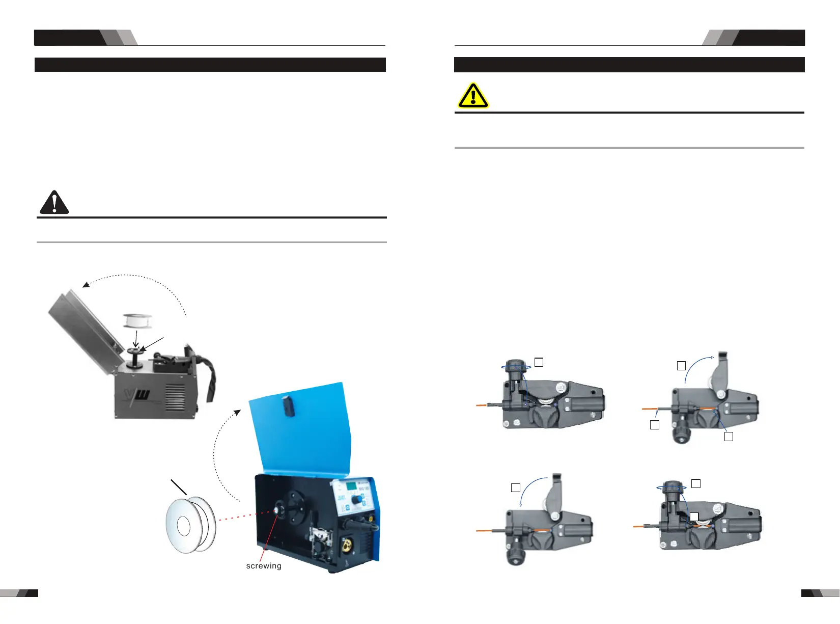
3.2 Installing spool
Install the spool, assemble the wire into the spool hub and replace the wire spool hub cover.
CAUTION
Use care in handling the spooled wire as it will tend to “unravel” when loosened from the spool.
Grasp the end of the wire firmly and don’t let go of it.
MIG SERIES EQUIPMENT MIG SERIES EQUIPMENT
Installation of wire spool:
1. Remove Wire Spool hub cover.
2. Place Wire Spool onto the hub, put back the hub cover back, turn securely to keep the wire
spool stable on the hub.
MIG185 / MIG225 diameter 200 (5kg/ mm)
MIG145 1 diameter 100 ( kg/ mm)
MIG255 / MIG295 1 diameter 265 ( 5kg/ mm)
MIG145 installation method
Welding wire
Welding wire
Unscrewing
Positioning pin
Unscrewing
Positioning pin
MIG185 / MIG225 / MIG255 /
MIG295 same installation
method
1. Loosen the Spring Pressure Adjusting Knob if needed and swing it down (See part 1) .
2. Move the Pressure (top) Roller Arm by swinging it to the right. (See part 2) .
3. Make sure the end of the wire is free of any burrs and is straight. Pass the end of wire
through the Inlet Wire Guide and over the Feed roll. Make certain the proper groove is
being used.(See part 2) .
3.3 Inserting wire into the feed mechanism
WARNING
ELECTRIC SHOCK CAN KILL! Make certain the input power is disconnected from the power
source before proceeding. DO NOT reattach the input power until told to do so in these
instructions.
7. Use the Spring Pressure Adjusting Knob to create a “snug” condition. (Clockwise to Tighten
and Counter Clockwise to loosen).
8. Last picture shows the result with wire installed. Continue to the next section for proper
setting of tension.
5. Close the Pressure Roller Arm.
6. Swing the Spring Pressure Adjusting Knob back into place.
4. Pass the MIG wire over the drive roll groove, through the outlet guide and out past the
MIG Torch Adaptor. Then fit the MIG Torch to ensure the MIG wire passes into the MIG
Torch liner of the MIG Torch.
MIG145 feed device
1
2
4
3
Illustration 1
7
6
5
Illustration 2