TCI-W13, TCI-W23 Universal Controller
OPERATION
Doc: 70-00-0365, V1.0, 20200304 © Vector Controls GmbH, Switzerland Page 3
Subject to alteration
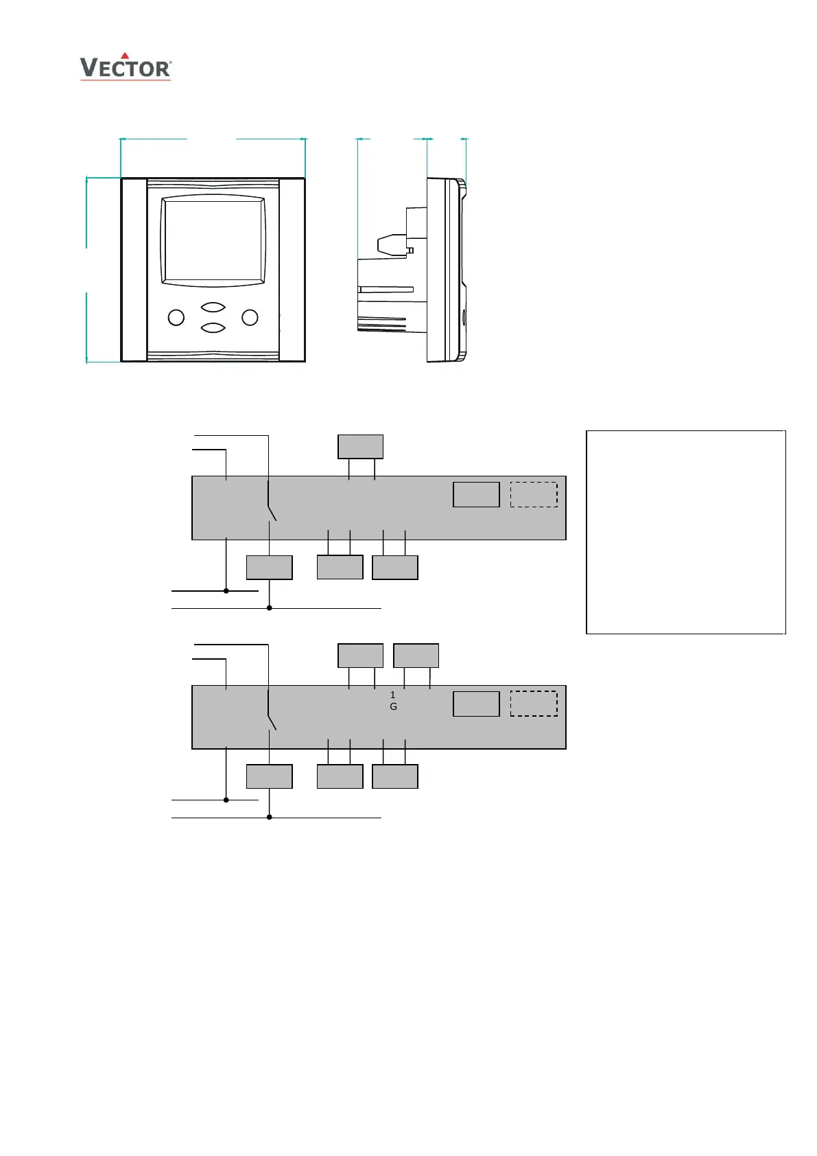
Dimensions, mm (inch) and Installation
Connection
Terminal Description
G0 Power supply: 0 V, -24 VDC; common for power supply, analog in- and outputs
G Power supply: 24 VAC, +24 VDC
X
U1
Universal input: NTC 10 kΩ @ 25 °C (77 °F) or open contact, 0…10 VDC or 0…20 mA
(selectable by jumper)
X
T2
Passive input: NTC 10 kΩ @ 25 °C (77 °F) or open contact
Y
B1
Binary output: Potential free relays contacts (see technical specification)
Y
M1,
X
M2
Analog outputs: 0…10 V or 0…20 mA
*
X
T1
Internal temperature input
X
H1
Internal humidity input if AES3-HT is inserted
Use copper, twisted pair, conductors only. The operating voltage must comply with the requirements for safety extra-low
voltage (SELV) as per EN 60730. Use safety insulating transformers class II with double insulation as per EN 60742; they
must be designed for 100% ON-time. When using several transformers in one system, the connection terminal 1 must be
galvanic connected. TCI is designed for operation of 24 VAC safety extra-low voltage and is short-circuit-proof. Supplying
voltages above 24 VAC to low voltage connections may damage the controller or other devices. Connection to voltages
exceeding 42 V endangers personnel safety.
Live electrical components!
During installation, testing, servicing
and troubleshooting of Vector
Controls products, it may be
necessary to work with live electrical
components. Have a qualified
licensed electrician or other
individual who has been properly
trained in handling live electrical
components perform these tasks.
Failure to follow all electrical safety
precautions when exposed to live
electrical components could result in
death or serious injury.
• Install the controller on an easy accessible
interior wall, approx. 1.5 m above the floor
in an area of average temperature.
• Avoid direct sunlight or other heat sources,
e.g. the area above radiators and heat
emitting equipment.
• Avoid locations behind doors, outside walls
and below or above air discharge grills and
diffusers.
• Location of mounting is less critical if
external temperature sensors are used.
• Ensure adequate air circulation to dissipate
heat generated during operation.
• Observe local regulations.
Do not mount in a wet or condensation
prone environments.

 Loading...


