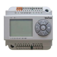
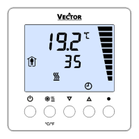
TCI-W13, TCI-W23 Universal Controller
INPUT CONFIGURATION
Doc: 70-00-0365, V1.0, 20200304 © Vector Controls GmbH, Switzerland Page 8
Subject to alteration
Control configuration (Password 241)
Input configuration
Internal inputs 1T temperature, 1H humidity for –H devices or with AES-HT inserted
Sensor sampling rate (control speed decrease as rate increases)
Low limit: Alarm 1 (1T), alarm 3 (1H), alarm 7 (2T)
Alarm 1/3 low limit values
High limit: Alarm 2 (1T), alarm (1H), alarm 8 (2T)
Alarm 2/4 high limit values
Hysteresis alarm 1, 2, 3, 4, 7, 8
Calculate a range of inputs (0 = not active):
1 = average, 2 = minimum, 3 = maximum, 4 = differential
Universal input 1U, external passive input 2T for TCI-W23
Signal type (0= not active):
1 = 0...10 V or 0...20 mA or open contact, 2 = 2...10 V or 4...20 mA,
3 = NTC temperature sensor
Analog input display range:
0 = x0.1, 1 = x1, 2 = x10, 3 = x100
Analog input unit of measure:
0 = no unit, 1 = %, 2 = °C/°F, 3 = Pa
Sensor sampling rate (control speed decrease as rate increases)
Alarm 5 low limit (1u), alarm 7 low limit (2t)
Alarm 5 low limit value (1u), alarm 7 low limit value (2t)
Alarm 6 high limit (1u), alarm 8 high limit (2t)
Alarm 6 high limit value 1u), alarm 8 high limit value (2t)
Hysteresis alarm 5 and 6 (1u), alarms 7 and 8 (2t)
Calculate a range of inputs (0 = not active):
1 = average, 2 = minimum, 3 = maximum, 4 = differential
➔ Set jumper for UI1 on the mounting plate: 0...10 VDC (default), 0...20 mA, or RT/DI (passive temperature NTC or
dry contact)
➔ Match sensor range to input display. With a differential pressure transmitter having 0...200 Pa measuring range set
UO1 display minimum to 0 and U02 display maximum to 200. The allowable range value of -50...205 may be
adjusted with multipliers in U03. The largest displayable values are -990...9999. Limiting range increases resolution.
Applies to analog as well as passive temperature inputs.
➔ For binary input (dry contact) set the jumper and parameter to RT/DI and change unit to % (1U04 = 1). An open
contact reads as a high value (100%), a closed contact as a low value (0%).
➔ Enable / Disable an alarm. Setting the alarm enable to OFF will prevent the alarm from being displayed on screen. It
may never the less be used to control an output by setting the appropriate output alarm flags. This way, an alarm
limit may be used as interlock.
➔ Specify the input value that triggers an alarm. Hysteresis is the difference between alarm level input and value
required to turn the alarm off. An alarm is displayed as text if enabled (see table). Alarm text can be set to blink
continuously until acknowledged by pressing the OPTION button or only while the alarm conditions are active (see
user parameter UP15).
➔ Calculate mathematical functions over multiple inputs for loop control or display with xU12. In order to calculate
average, minimum or maximum between several inputs, make sure all the inputs are of identical type and range and
then activate the same function on xU12 on all the selected inputs. The largest input of the group selected will carry
the calculated value. For example: When average is activated on 2T12 and 1U12 = 1, the average is carried on UI2.
UI2 may now be used as input for control loops and it will show the average value of UI1 and TI2 combined. It is
possible to use different functions on different inputs.
➔ The differential function may only be calculated on subsequent inputs. Such as TI2-UI1. The function must only be
activated on the minuend (TI2 in this example). The displayed value of the minuend will change into the difference:
TI2 in – UI1 = TI2 out. It is possible to have multiple differentials on one controller. It is not possible to reverse the
subtraction to UI1-TI2.
 Loading...
