EasyManuals Logo
Home>Veeder-Root>Music Mixer>TLS-3 Series

Veeder-Root TLS-3 Series Site Prep And Installation Manual

Veeder-Root TLS-3 Series
91 pages
To Next Page IconTo Next Page
To Previous Page IconTo Previous Page
Page #20 background imageLoading...
Page #20 background image
Console Installation Wiring the Console
14
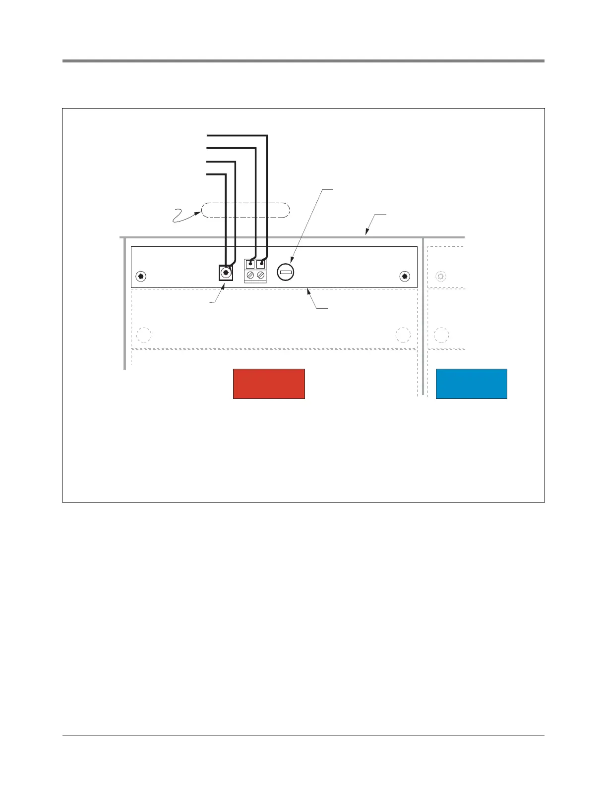
Figure 8. Wiring AC Power to the TLS-350/ProMax/EMC Console
CHECKING THE GROUND CONNECTION
Use an ohmmeter to check the electrical resistance between the console’s metal case and the earthing ground
wire’s connection at the “known good earth ground”. It should read less than 1 ohm.
Rigid Conduit
(enters Through
a Power Bay
knockout)
Top of
Console
NL
1
Barrier Ground
(#12 AWG or larger)
Chassis Ground
AC Neutral
AC Line (hot)
POWER BAY
POWER BAY
INTRINSICALLY
SAFE BAY
consoles\pwrmwir.eps
F
U
S
E
F
U
S
E
2A, Slo-Blo (5 mm x 20 mm)
POWER MODULE
POWER WIRING NOTES:
1. Barrier ground must be #12 AWG or larger.
2. Check to be sure that the electrical resistance between the console ground
lug and a known good earth ground is less than 1 ohm.
3. Connect the power supply wires in the power panel to a separate dedicated circuit.
4. Electrical rating power input -- 120 Vac or 240 Vac, 50/60 Hz, 100 W maximum.
5. See the "Console Dimensions and Designated Conduit Knockouts" diagram for
actual locations of power conduit knockouts into the console. Power wiring conduits
must enter Power Bay knockouts.
Use ground lug
closest to conduit
entry

Table of Contents

Other manuals for Veeder-Root TLS-3 Series

Questions and Answers:

Question and Answer IconNeed help?

Do you have a question about the Veeder-Root TLS-3 Series and is the answer not in the manual?

Veeder-Root TLS-3 Series Specifications

General IconGeneral
BrandVeeder-Root
ModelTLS-3 Series
CategoryMusic Mixer
LanguageEnglish

Related product manuals