Connecting Probe/Sensor Wiring to Consoles TLS-300/ProPlus/EMC Basic Consoles
55
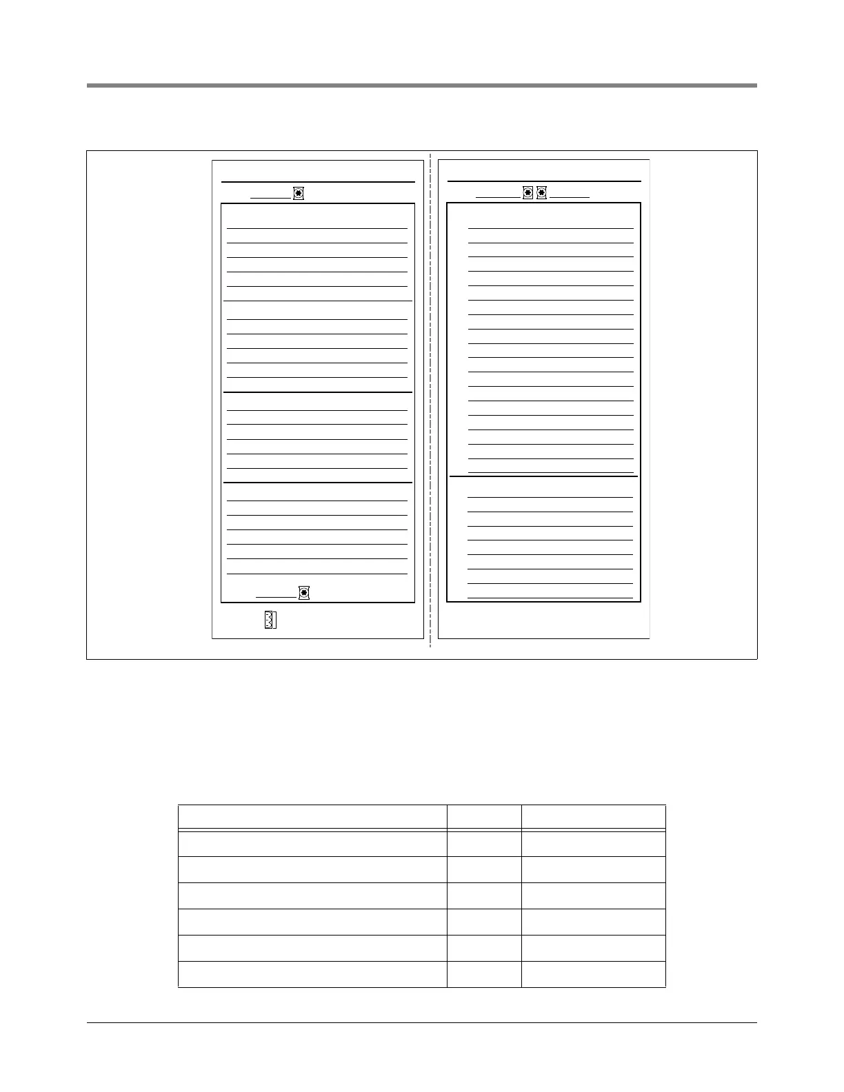
Figure 53. Fixed-Feature Console System Circuit Directory
CONNECTING PROBES AND SENSORS TO THE CONSOLE
Figure 54 contains wiring connection examples for the probes and sensors listed below. Only ground the probe/
sensor shields at the console, not at their field junction boxes. Probes wires connect to the probe terminal block
and sensors connect to the sensor terminal block.
Device Wires Observe Polarity
Mag Probe 2 Yes
Interstitial sensors for fiberglass/steel tanks 2 No
Sump sensors 2 No
Discriminating Dispenser Pan sensors 2 No
Discriminating containment sump sensors 2 No
Hydrostatic sensors (for all double-wall tanks) 2 No
POWER AREA
GROUND
INPUT 1
Connected to:
INPUT 2
Connected to:
RELAY 1
Connected to:
RELAY 2
Connected to:
GROUND
AC POWER
L1
G
N
INTRINSICALLY SAFE AREA
GROUND
SENSOR LOCATIONS
1.
2.
3.
4.
5.
6.
7.
8.
9.
10.
11.
12.
13.
14.
15.
16.
17.
18.
PROBE LOCATIONS
1.
2.
3.
4.
5.
6.
7.
8.
consoles\30cirdir.eps
BACKUP GENERATOR
OVERFILL ALARM OUT
TANK 1 - INTERSTIAL
TANK 1 - SUMP
TANK 2 - INTERSTIAL
TANK 2 - SUMP
TANK 1 - REGULAR
TANK 2 - PLUS
TANK 3 - INTERSTIAL
TANK 3 - SUMP
TANK 3 - EXTRA
 Loading...