Sensor Installation Sensor Installation Diagrams
42
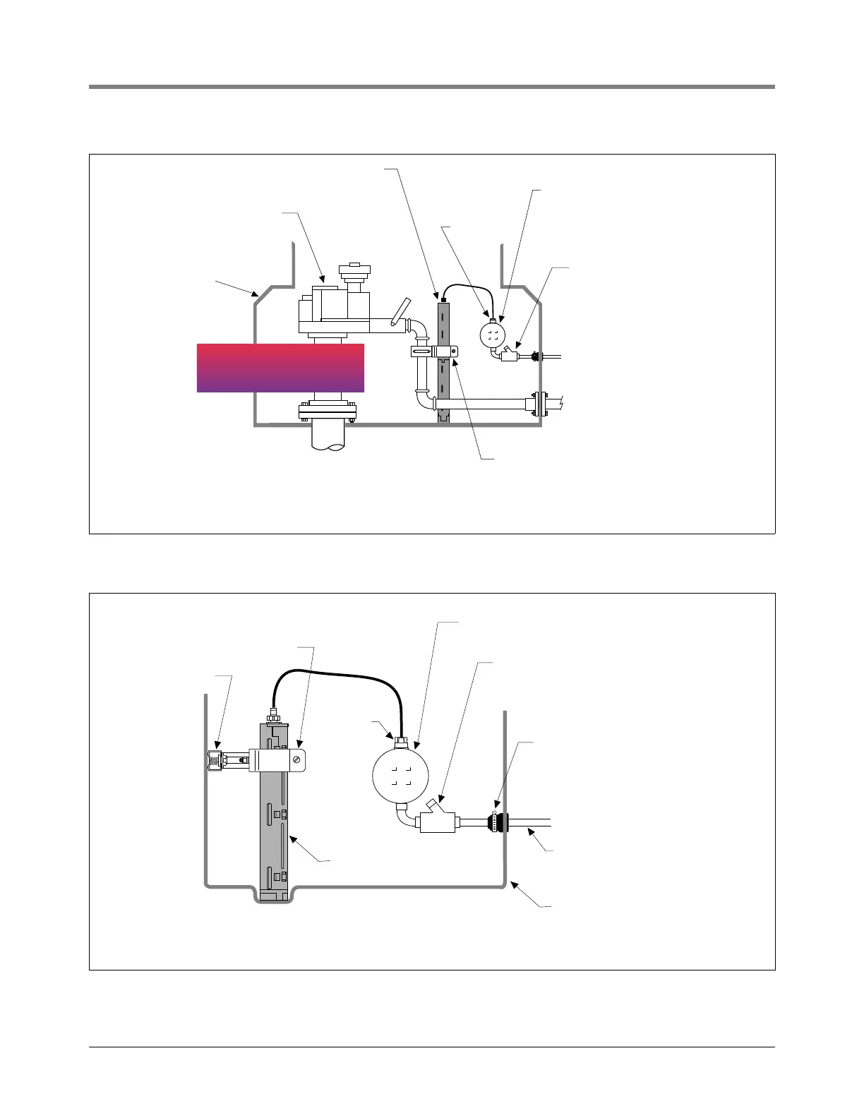
Figure 37. Example Containment Sump Sensor Installation
Figure 38. Example Dispenser Pan Sensor Installation
Submersible
pump
Containment
sump
Containment
sump sensor
*
Weatherproof junction
box with 1/2-inch N.P.T.
threads (16 cubic inch
volume minimum)
1/2'' Rigid conduit
to console
Seal-off
sensors\cssinst.eps
Cord grip
Product line
*
Containment sump sensor should:
1. Rest in the lowest point of sump.
2. Be positioned as close to outer wall as possible.
3. Be mounted in a true vertical position.
Brackets, clamp, etc., from
Universal sensor mounting kit
IMPORTANT!
DO NOT MOUNT SENSOR TO
FLEXIBLE PRODUCT LINE.
IMPORTANT!
DO NOT MOUNT SENSOR TO
FLEXIBLE PRODUCT LINE.
Rubber grommet seal
clamped on inside -
or as recommended by
dispenser pan manufacturer.
Weatherproof junction box with 1/2-inch N.P.T.
threads (16 cubic inch volume minimum).
1/2'' Rigid conduit
to console
Seal-off
Cord grip
Brackets, clamp, etc.,
from Universal sensor
mounting kit
*Dispenser pan sensor should:
1. Rest in the cup or the lowest point of the dispenser pan.
2. Be positioned so as to be removable by pulling the sensor straight up out of the pan.
3. Be mounted in a true vertical position.
Dispenser pan sensor*
Dispenser pan
sensors\dpsinst.eps
U-channel

 Loading...